
Airbag and airbag apparatus

a technology of airbags and airbags, which is applied in the direction of pedestrian/occupant safety arrangements, vehicular safety arrangments, vehicle components, etc., can solve the problems of excessive volume of airbags, overleaving the lateral overhanging portion of airbags, and large gas-generation volume of inflators

Inactive Publication Date: 2006-07-27
TAKATA CORPORATION
View PDF15 Cites 73 Cited by
  • Summary
  • Abstract
  • Description
  • Claims
  • Application Information

AI Technical Summary

Benefits of technology

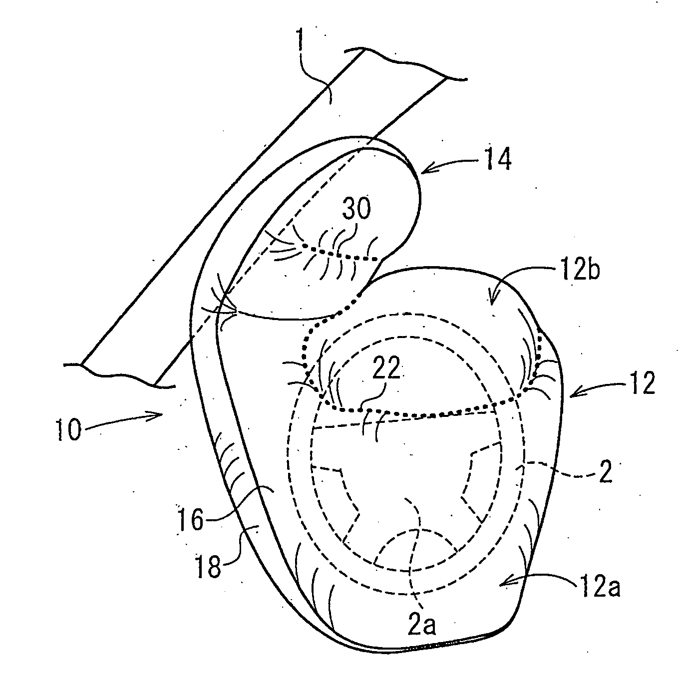
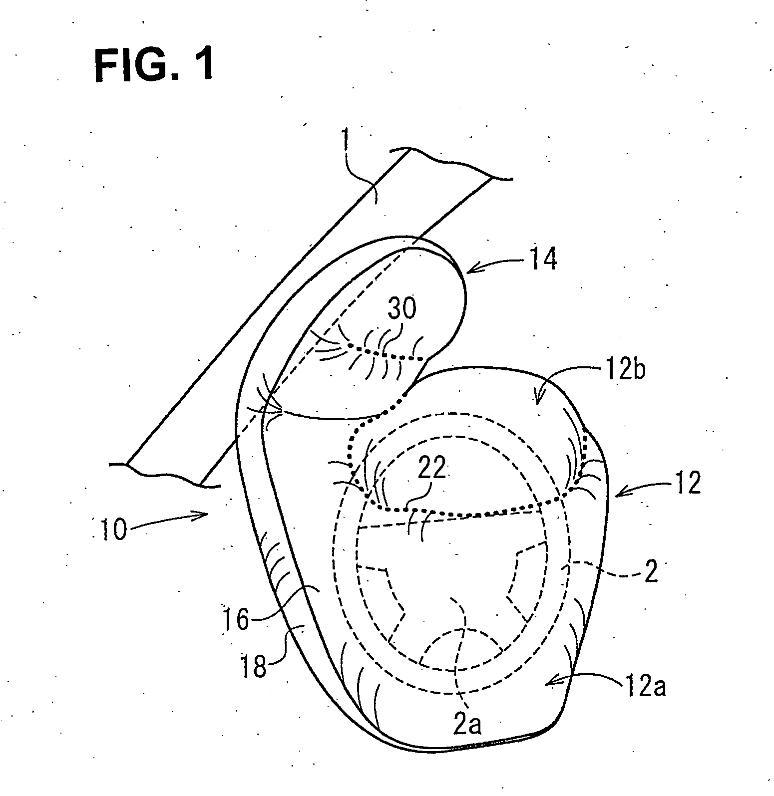
[0016] In the airbag according to the invention, the upper extending portion is extended upward from above a left or a right side of the airbag main body. Because the upper extending portion, when the airbag is expanded, is extended upward along the pillar and covers the pillar, a head region of the occupant is prevented from colliding with the pillar, even when the occupant moves upward in an obliquely forward direction.
[0017] Particularly, by determining the extending length L of the upper extending portion from the airbag main body, when expanded, in the direction parallel to the axial direction of the steering column to be from 50 to 400 mm, the head region of the occupant is sufficiently prevented from colliding with the pillar.
[0021] When the airbag apparatus is applied for use in a driver-side seat, the airbag apparatus is configured so as to not change the posture (i.e., shape and position) thereof, even when a steering wheel is rotated. As a result, even when the motor vehicle is crashed while moving through a curve, the upper extending portion is reliably expanded along the A pillar.

Problems solved by technology

When the volume of the airbag is increased, most of a head region and an upper half of the body of the occupant can be caught by the airbag, however, a large gas-generation volume is required for an inflator.
Therefore, in the event of an oblique crash of the motor vehicle, and when an occupant moves in a manner stretching upward in an obliquely forward direction, there is a possibility that a head region of the occupant collides with a pillar, overleaping the lateral overhanging portion of the airbag.
In the airbag having increased lengths in an upper-and-lower direction and a left-and-right direction for preventing the above problem, the volume of the airbag becomes excessive.

Method used


Image

  • Airbag and airbag apparatus
  • Airbag and airbag apparatus
  • Airbag and airbag apparatus

Examples


Embodiment Construction

[0029] The embodiments of the present invention will be described below with reference to the accompanying drawings.

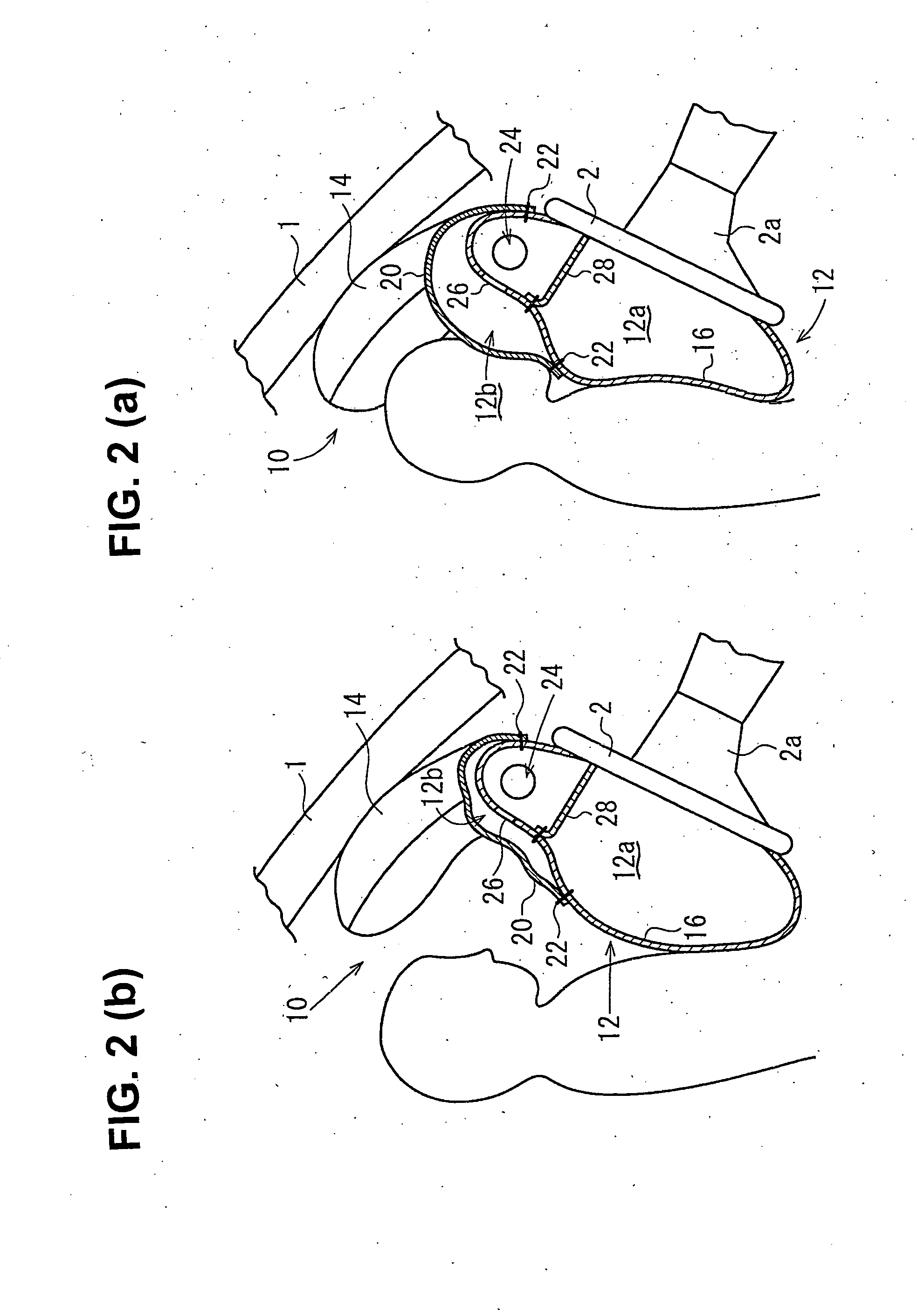
[0030]FIG. 1 is a perspective view illustrating an embodiment of an airbag, when expanded; FIG. 2(a) is a vertical cross-section illustrating the airbag, when a first chamber thereof is expanded; FIG. 2(b) is a vertical cross-section illustrating the airbag when a second chamber thereof is expanded; FIG. 3 is a plan view of the airbag; FIG. 4 is a side view of an interior of a motor vehicle when the airbag is expanded; and FIG. 5 is a perspective view of the airbag when an upper extending portion thereof catches a head region of an occupant.

[0031] In this embodiment, an airbag 10 is the driver-side airbag mounted on a driver-side airbag apparatus of the motor vehicle. The driver-side airbag apparatus is provided with the airbag 10, a retainer (not shown), to which the airbag 10 is attached, a gas-generator (not shown) for expanding the airbag 10, and a module cover (...


PUM


Abstract

An airbag of an airbag apparatus includes an airbag main body capable of expanding in a manner such that the airbag main body covers a steering wheel in front of a driver seated in a driver-side seat, and an upper extending portion that covers a vehicle roof pillar by extending upward from above a left or right side of the airbag main body. The airbag apparatus is designed so as to maintain the airbag shape and position even when the steering wheel is rotated. In the event of an oblique collision, the airbag is capable of preventing a head region of a driver from colliding with the pillar, yet without excessively increasing the required airbag volume.

Description

BACKGROUND OF THE INVENTION AND RELATED ART STATEMENT [0001] The present invention relates to an airbag and an airbag apparatus attached to a motor vehicle or the like, and more specifically relates to an airbag and an airbag apparatus configured to prevent a head region of an occupant from colliding with a pillar of the motor vehicle. [0002] An airbag for protecting an occupant seated on a driver's seat, a passenger seat, or a rear seat of a motor vehicle, in the event of a crash of the motor vehicle, is known. When the volume of the airbag is increased, most of a head region and an upper half of the body of the occupant can be caught by the airbag, however, a large gas-generation volume is required for an inflator. [0003] A passenger airbag that prevents the head region of the occupant from colliding with a pillar of the motor vehicle and that attempts to minimize gas volume is described in U.S. Pat. No. 4,474,390. FIG. 6 illustrates the airbag described in U.S. Pat. No. 4,474,390...

Claims


Application Information

Patent Timeline
Patent Type & Authority Applications(United States)
IPC IPC(8): B60R21/231B60R21/233B60R21/16B60R21/203B60R21/2338
CPCB60R21/2032B60R21/231B60R21/233B60R2021/0009
Inventor ABE, KAZUHIRO
Owner TAKATA CORPORATION
Learn More