Eureka AIR delivers breakthrough ideas for toughest innovation challenges, trusted by R&D personnel around the world.

Air cushion with selectively deflated chambers

a cushion and chamber technology, applied in the field of air cushions, can solve the problem of expensive multi-small air pouches

Inactive Publication Date: 2006-08-03
TSAY REN JI
View PDF23 Cites 10 Cited by
  • Summary
  • Abstract
  • Description
  • Claims
  • Application Information

AI Technical Summary

Benefits of technology

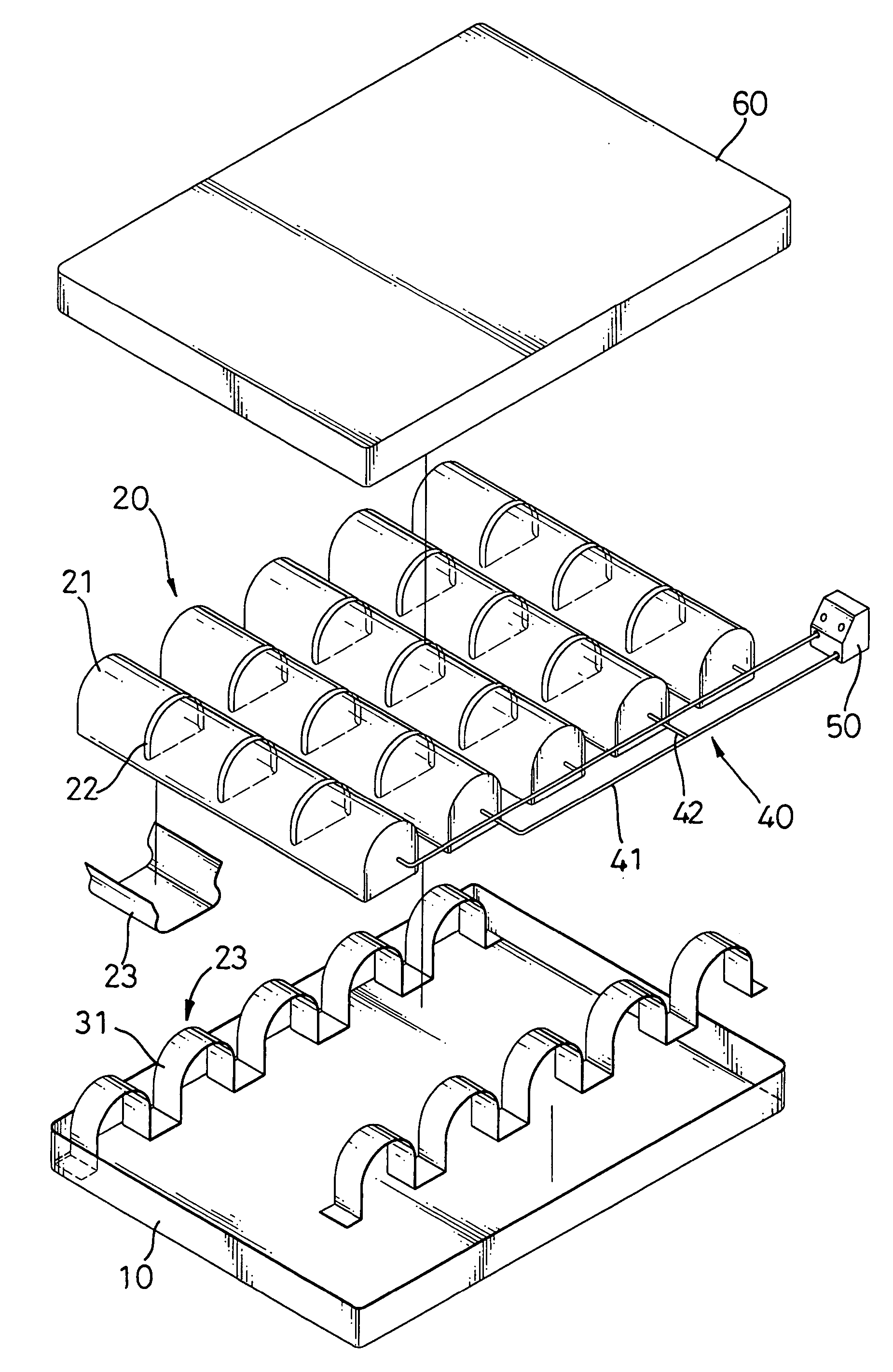
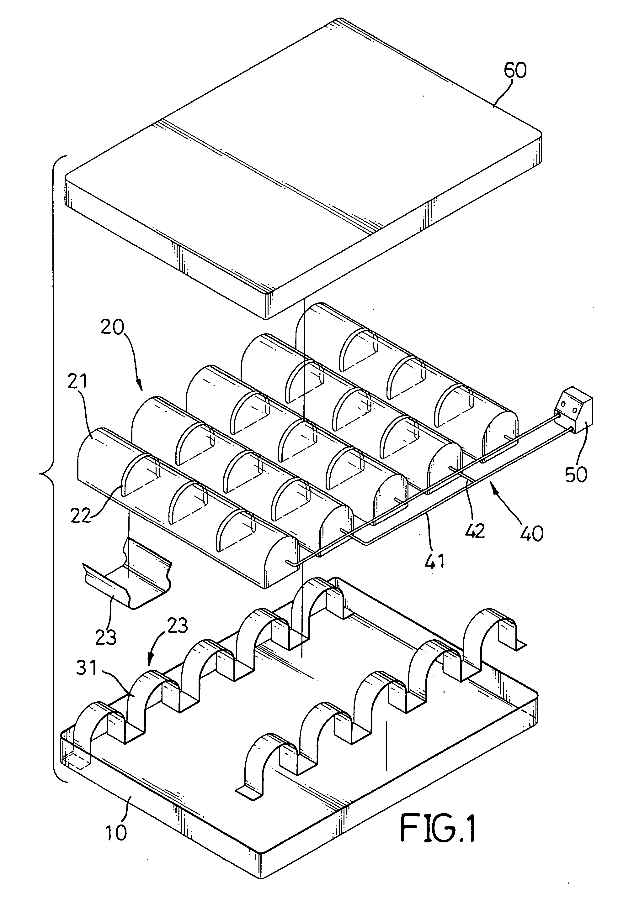
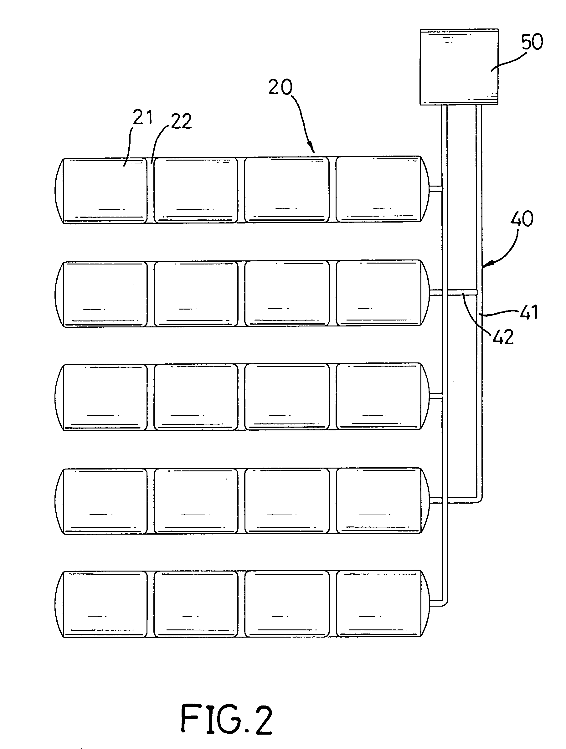
[0006] The main objective of the present invention is to provide an air cushion with selectively deflated chambers that has multiple air pouches with multiple chambers. The air cushion with selectively deflated chambers has a base, multiple air pouches, multiple attachment devices, at least two air tube, an air pump and a cover sheet. The air pouches are mounted on the base, and each air pouch has an inner space and multiple compression straps. The inner space is divided into multiple chambers that communicate with one another. Each compression strap keeps a selected chamber of the air pouch from inflating. The attachment devices are mounted on the base to attach the air pouches to the base. The at least two air tube connects to the air pouches and communicates with the inner spaces of the air pouches. The air pump connects to and pumps air through the air tube into the air pouches. Any one of the chambers can be kept from inflating if the chamber is going to contact injured skin of a patient.

Problems solved by technology

However, the user has to find other spaces to stow the removed air pouches and making multiple small air pouches is expensive.

Method used


Image

  • Air cushion with selectively deflated chambers
  • Air cushion with selectively deflated chambers
  • Air cushion with selectively deflated chambers

Examples


Embodiment Construction

[0011] With reference to FIG. 1, an air cushion with selectively deflated chambers in accordance with the present invention comprises a base (10), multiple air pouches (20), multiple attachment devices (30), at least two air tube (40), an air pump (50) and a cover pad (60).

[0012] The base (10) has a top surface.

[0013] With further reference to FIGS. 2 and 3, the air pouches (20) are mounted on the top surface of the base (10). Each air pouch (20) has a top, a bottom, an inner space, at least one partitioning gap (22) and multiple compression straps (23). The inner space is divided into multiple chambers (21) that communicate with one another. The at least one partitioning gap (22) is formed in the top, and each partitioning gap (22) separates adjacent chambers (21). The compression straps (23) are selectively mounted respectively over the chambers (21) to keep selected chambers (21) from inflating. After the compression straps (23) are mounted over the selected chamber (21), the c...


PUM


Abstract

An air cushion with selectively deflated chambers has a base, multiple air pouches, multiple attachment devices, at least two air tube, an air pump and a cover sheet. The air pouches are mounted on the base, and each air pouch has an inner space and multiple compression straps. The inner space is divided into multiple chambers that communicate with each other. Each compression strap keeps a selected chamber of the air pouch from inflating. The attachment devices are mounted on the base to attach the air pouches to the base. The at least two air tube connects to the air pouches and communicates with the inner spaces of the air pouches. The air pump connects to and pumps air through the air tube into the air pouches. Any one of the chambers can be kept from inflating if the chamber contacts injured skin of a patient.

Description

BACKGROUND OF THE INVENTION [0001] 1. Field of the Invention [0002] The present invention relates to an air cushion, especially to an air cushion that has selectively deflated chambers. [0003] 2. Description of the Prior Arts [0004] Air cushions can be mattresses for patients who have injuries to the skin or have bedsore. With reference to the U.S. Pat. No. 6,671,912 entitled “Modulated air cushion,” a conventional air cushion comprises a base, multiple air pouches, multiple tubes, an air pump and a cover sheet. The base has bonding elements. The air pouches are attached on the bonding elements and have corresponding bonding elements by which the air pouches are attached to the base. The tubes connect to and communicate with the air pouches. The air pump pumps air through the tubes into the air pouches. Any one of the air pouches can be removed depending on the need to relieve pressure on a specific area that cannot have any air pouches, such as injured skin of a patient. However, t...

Claims


Application Information

Patent Timeline
IPC IPC(8): A47C27/10
CPCA61G7/05776A61G2005/1045A61G5/1045
Inventor TSAY, REN-JI
Owner TSAY REN JI
Why Eureka
Eureka Blog
Learn More