Method for driving light deflector, light deflector, light deflection array, image forming device, and image projection display apparatus

a technology of image forming device and driving light, which is applied in the direction of optics, instruments, optics, etc., can solve the problems of high cost of manufacturing projection-type image forming device, high cost of response speed, and difficulty in ensuring beam stability

Inactive Publication Date: 2006-08-03
RICOH KK
View PDF21 Cites 7 Cited by
  • Summary
  • Abstract
  • Description
  • Claims
  • Application Information

AI Technical Summary

Benefits of technology

[0017] Accordingly, it is a general object of the present invention to provide a novel and useful method for driving light deflector, light deflector, light deflection array, image forming device, and image projection display apparatus, in which one or more of the problems described above are eliminated.
[0018] More specifically, the object of the present invention is to provide a light deflector whereby it is easy to stably control a deflection angle of a mirror, response speed is high, there is little degradation for a long period of time, it is possible to drive at a lower voltage, it is possible to improve the ratio of on / off of the reflection light (S / N ratio in an image device or a contrast ratio in a picture device), it is possible to achieve miniaturization and integration at a low cost, and it is possible to do two-dimensional light deflection in one axial direction or three-dimensional light deflection in two axial directions. It is another object of the present invention to provide a method for driving the light deflector whereby an error operation due to storage of electrical charge can be controlled.

Problems solved by technology

However, since the laser light source is required from the perspective of the optical switch, the cost for manufacturing the projection type image forming device is made high.
The above-discussed optical switch using the cantilever beam or the cantilever type digital micro mirror device has weak points, that is, difficulty in ensuring stability of the beam and difficulty in making the response speed high.
Furthermore, the torsion beam type digital micro mirror device also has a weak point in that mechanical strength of a hinge part (torsion beam) is degraded when used for a long period of time.
In addition, the optical switch discussed in Japanese Patent 2941952 and Japanese Patent 3016871 has a weak point in that the wavelength of the incident light is limited.
However, in this element, since both ends are fixed, it is not possible to make the driving voltage as low as the device of the cantilever beam type or torsion beam type.
This causes an incorrect action of the light deflection device, for example.

Method used


Image

  • Method for driving light deflector, light deflector, light deflection array, image forming device, and image projection display apparatus
  • Method for driving light deflector, light deflector, light deflection array, image forming device, and image projection display apparatus
  • Method for driving light deflector, light deflector, light deflection array, image forming device, and image projection display apparatus

Examples


first embodiment

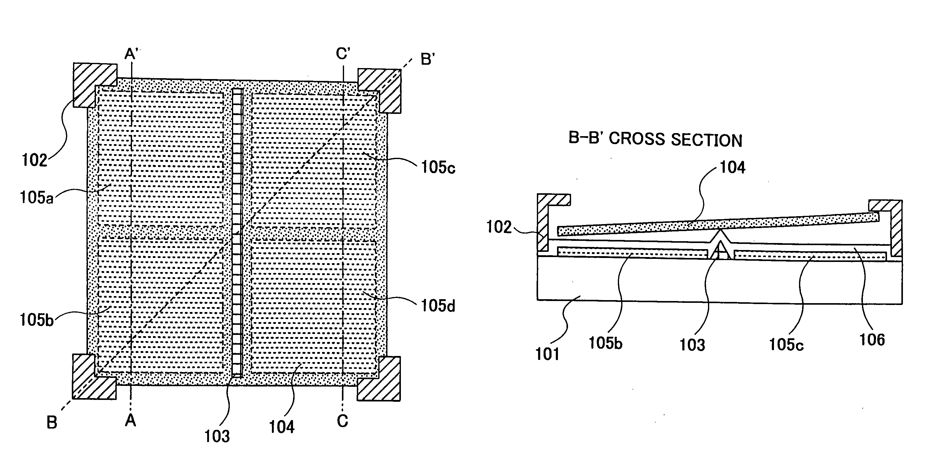
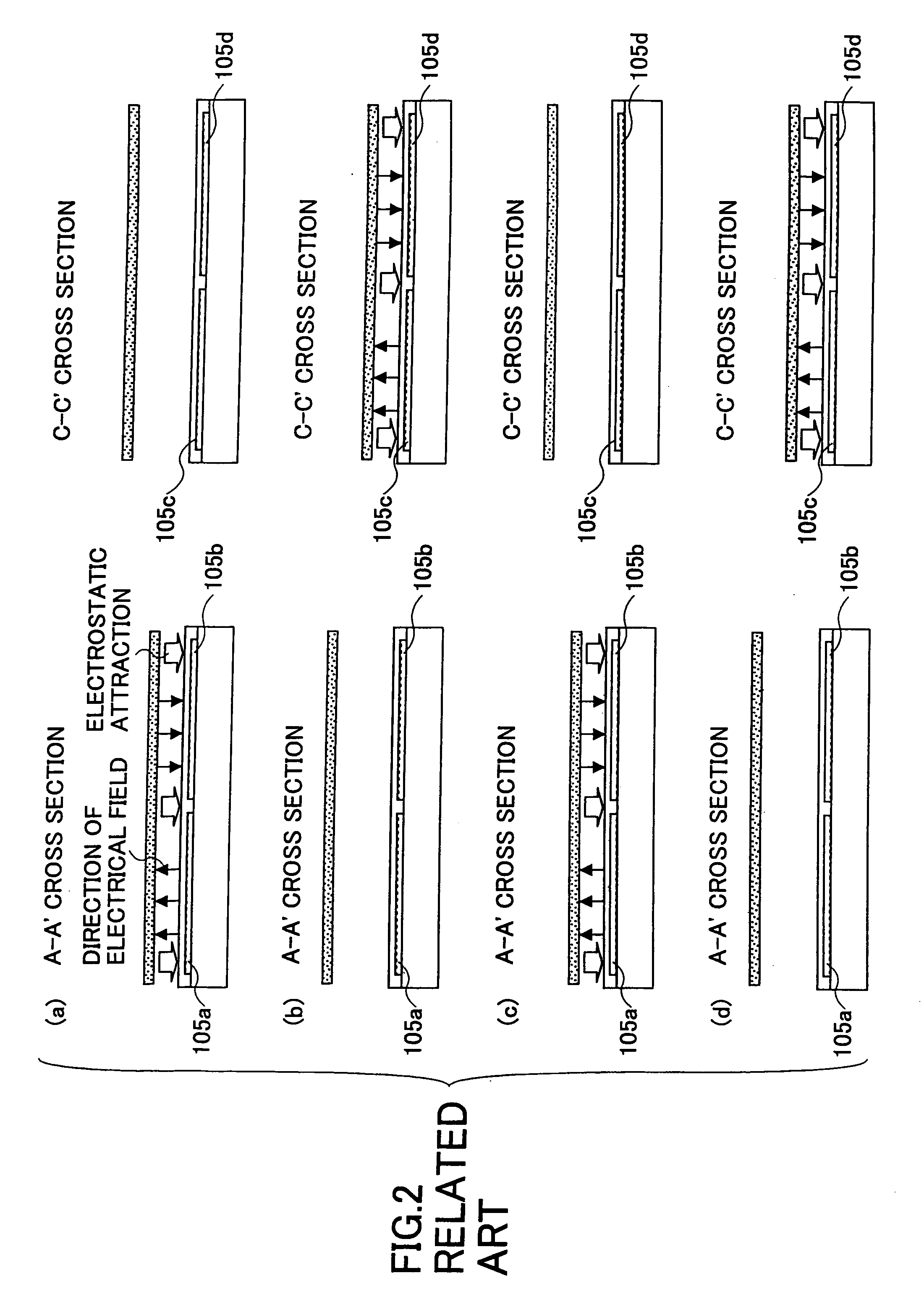
[0133]FIG. 5 is a cross-sectional view showing a method for driving a light deflector of the first embodiment of the present invention. The first embodiment is an example wherein the light deflector of the present invention shown in FIG. 4 is stably light-deflection-operated. FIG. 5-(a) through FIG. 5-(d) are cross-sectional views of the light deflector taken along the planes A-A′ and C-C′ at the time of light deflection operations. FIG. 5-(a) corresponds to step 1. FIG. 5-(b) corresponds to step 2. FIG. 5-(c) corresponds to step 3. FIG. 5-(d) corresponds to step 4.

[0134] Directions of electrical fields generated by electric potentials applied to the electrodes 105a-105d are shown by black arrows and electrostatic attractions shown by white arrows in FIG. 5-(a), FIG. 5-(b), FIG. 5-(c), and FIG. 5-(d).

[0135]FIG. 6 is a timing chart of electric potentials applied to electrodes in the method for driving the light deflector of the first embodiment. In FIG. 6, the electric potential “a...

second embodiment

[0142]FIG. 7 is a timing chart of electric potentials applied to electrodes in the method for driving the light deflector of the second embodiment. In FIG. 7, an electric potential “x” is an electric potential having a half value of a positive electric potential. Referring to FIG. 7, the method for driving the light deflector of the second embodiment of the present invention and tilt displacement operations (light deflection operations) of the plate shape member 104 corresponding to the method are discussed. In the method for driving the light deflector of the second embodiment of the present invention, an electric potential of either of different electric potentials of the method for driving the light deflector of the first embodiment is a positive electric potential, another electric potential of different electric potential of the method for driving the light deflector of the first embodiment is ground potential, and an intermediate electric potential is a half of the positive el...

third embodiment

[0149]FIG. 8 is a timing chart of electric potentials applied to electrodes in the method for driving the light deflector of the third embodiment. In FIG. 8, although the polarity of a positive electric potential is different from the polarity of a negative electric potential, both of them have substantially the same value. Referring to FIG. 8, the method for driving the light deflector of the third embodiment of the present invention and tilt displacement operations (light deflection operations) of the plate shape member 104 corresponding to the method are discussed. In the method for driving the light deflector of the third embodiment of the present invention, an electric potential of either of different electric potentials of the method for driving the light deflector of the first embodiment is a positive electric potential, another electric potential of the different electric potentials of the method for driving the light deflector of the first embodiment is a negative electric ...


PUM


Abstract

A method for driving a light deflector the method includes turning over a direction of an electric field acting on the plate shape member, in an optional period. In the method, the light deflector deflects a beam incident on a light reflection area by displacing a plate shape member having the light reflection area with an electrostatic force. The light deflector includes a substrate, a plurality of control members, a fulcrum member, the plate shape member, and a plurality of electrodes.

Description

BACKGROUND OF THE INVENTION [0001] 1. Field of the Invention [0002] The present invention generally relates to methods for driving light deflectors whereby the direction of outgoing light against incident light is changed. For example, the present invention can be used for image forming devices such as electrophotographic type printers or copiers, or projection type image display apparatuses such as projectors or digital theater systems. [0003] 2. Description of the Related Art [0004] As an optical switch device using an electrostatic force, a device wherein a cantilever is deformed by an electrostatic force so that a reflection direction of light is changed (switched) and a light deflection system using the device were published by K. E. Petersen in 1977. See “Applied Physic Letters, Vol. 31, No. 8, page 521 to page 523”, Japanese Patent No. 2941952, and Japanese Patent No. 3016871. In addition, D. M. Bloom et al. published an element wherein a diffraction grating is driven by an e...

Claims


Application Information

Patent Timeline
Patent Type & Authority Applications(United States)
IPC IPC(8): G02B26/00G02B26/10G02B26/08
CPCG02B26/0841
Inventor NANJYO, TAKESHIKATOH, SEIICHIOHTAKA, KOUICHI
Owner RICOH KK
Why Eureka
Try Eureka