Shelf bracket lock

a technology for shelf brackets and locks, which is applied in the field of shelf brackets, can solve the problems of ineffective use of prior art brackets for both solid and wire shelves, and is difficult if not impossible to us

Active Publication Date: 2006-08-10
RUBBERMAID
View PDF20 Cites 37 Cited by
  • Summary
  • Abstract
  • Description
  • Claims
  • Application Information

AI Technical Summary

Problems solved by technology

However, the presence of the clamp on a wire-shelf bracket obstructs the shelving plane defined by the upper surface of the bracket and makes the use of

Method used


Image

  • Shelf bracket lock
  • Shelf bracket lock
  • Shelf bracket lock

Examples


Embodiment Construction

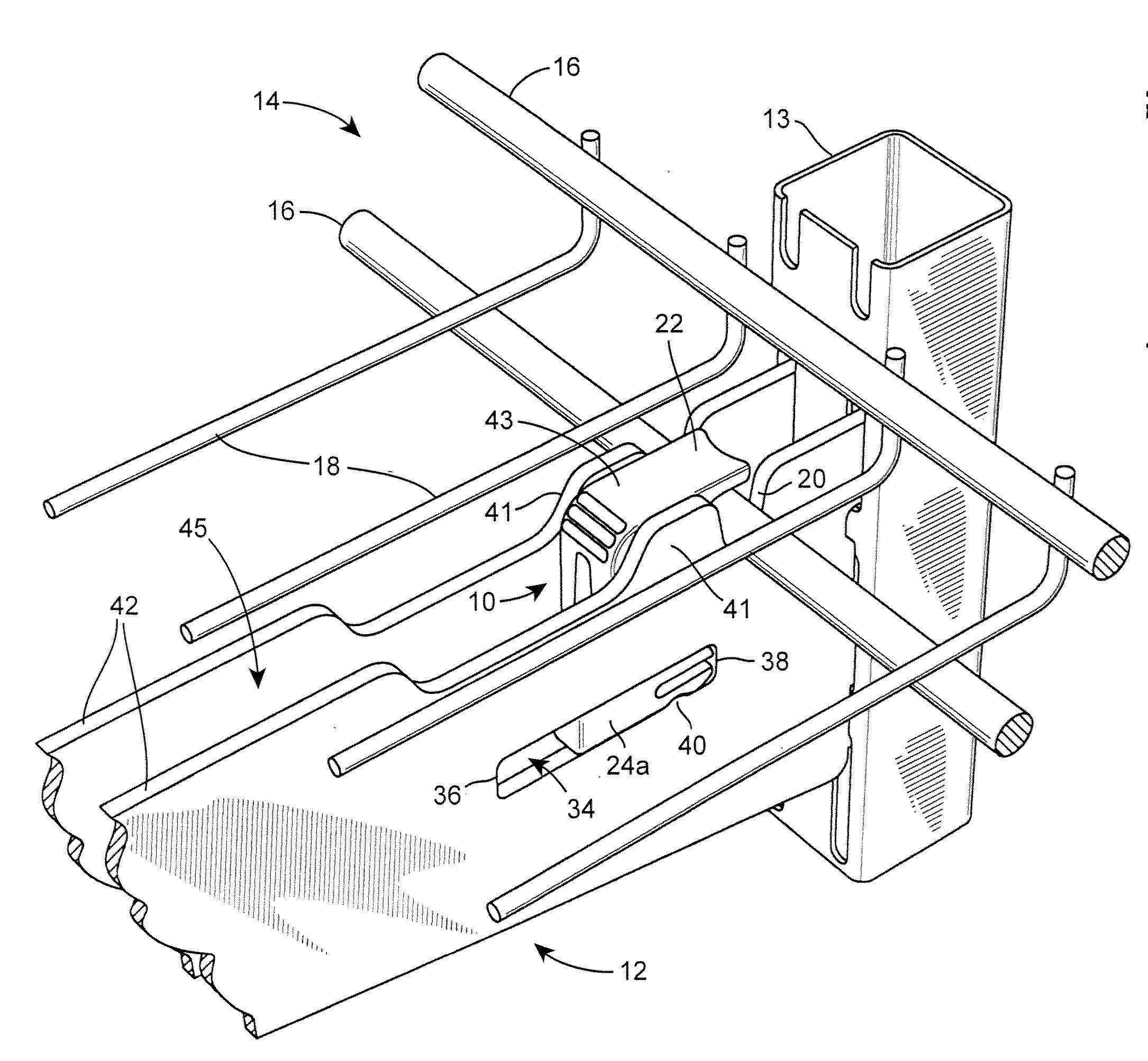
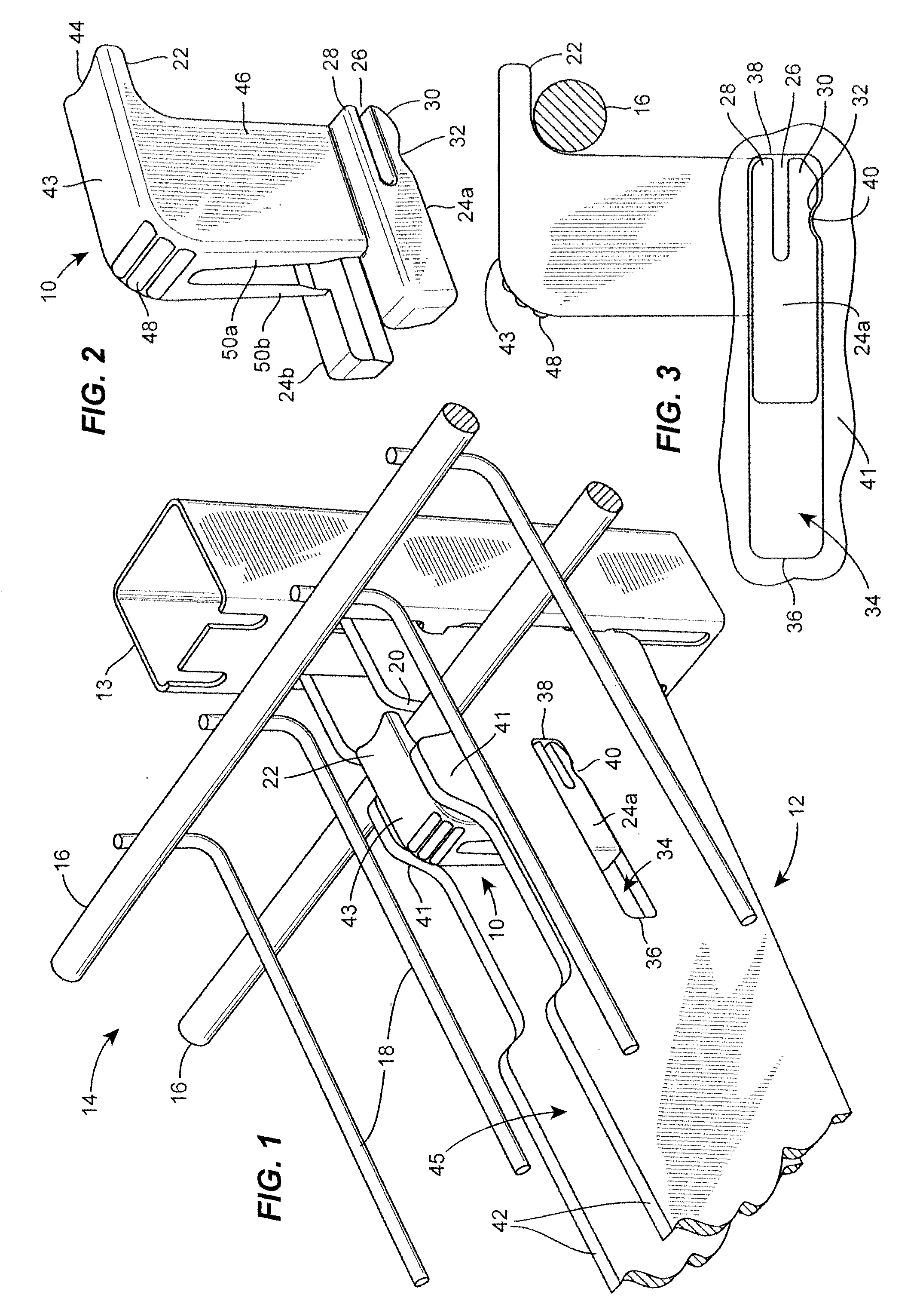
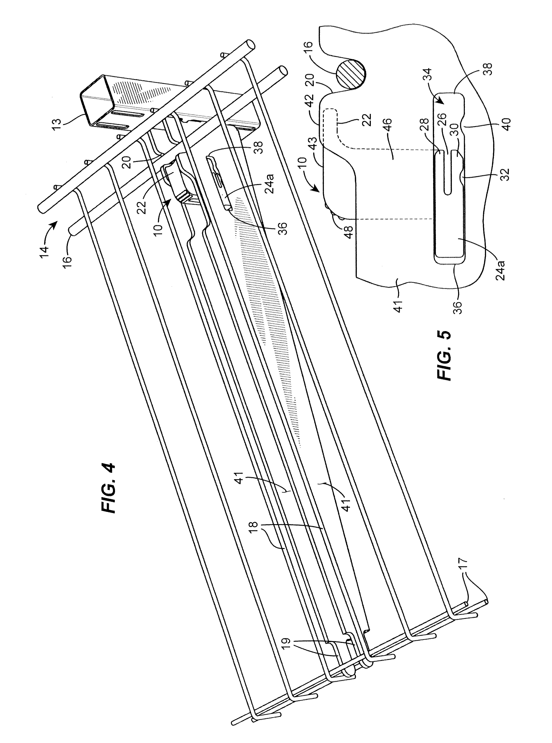
[0010] The bracket lock and bracket described herein in accordance with the teachings of the present disclosure solve or improve upon the problems and limitations described above, as well as other deficiencies, that are known in the prior art. For example, the disclosed shelf bracket lock can be used with a shelf bracket operable for supporting either a wire shelf or a solid shelf because the bracket lock is designed to either be flush with or extend above a top surface of the bracket and thus does not obstruct a solid shelf from lying flat on the top surface of the bracket. A wire shelf is secured by placing the shelf into a groove formed in the shelf bracket. The bracket lock is urged in a horizontal direction so as to constrain the wire within the groove of the shelf. The shelf bracket and shelf bracket lock can be made of any suitable material such as plastic, metal, or composite. Plastic material can be made from polypropylene, nylon, or acetal, but is not limited to these mate...


PUM


Abstract

A locking bracket system comprises a bracket lock and a bracket. The bracket lock may be slidably positioned along the lateral length of the bracket to transition between locked and unlocked configurations. When locked, an upper cantilever tab on the bracket lock secures a wire frame shelf that is recessed in a groove on the bracket. When unlocked, the wire frame shelf is not obstructed by the bracket shelf lock and may be removed. A solid shelf may be used in combination with the locking bracket system, as the bracket shelf lock does not obstruct the shelving plane upon which the solid shelf sits.

Description

RELATED APPLICATION DATA [0001] This application claims priority to U.S. Provisional application No. 60 / 637,983, filed Dec. 21, 2004, as to all subject matter commonly disclosed therein.FIELD OF THE DISCLOSURE [0002] The present invention generally relates to a shelf bracket for use with a wire shelf or a solid shelf, and more particularly to a shelf bracket having a lock for locking a wire shelf to the bracket. BACKGROUND OF THE DISCLOSURE [0003] Brackets for shelving have been traditionally designed specifically for one particular style of shelf, namely, either a wire shelf or a solid shelf made out of metal, wood, plastic, or the like. Brackets for wire shelves typically include at least one groove for receiving a wire formed on the wire shelf. A clamp can be employed to prevent removal of the wire from the groove of the bracket. However, the presence of the clamp on a wire-shelf bracket obstructs the shelving plane defined by the upper surface of the bracket and makes the use of...

Claims


Application Information

Patent Timeline
IPC IPC(8): A47G29/02
CPCA47B96/028
Inventor GREGORY, MICHAEL A.
Owner RUBBERMAID
Why Eureka
Try Eureka