Control server, control terminal, control system, and recording medium storing control communication program
Active Publication Date: 2006-08-10
SCHNEIDER ELECTRIC JAPAN HLDG LTD
View PDF12 Cites 32 Cited by
Summary
Abstract
Description
Claims
Application Information
AI Technical Summary
This helps you quickly interpret patents by identifying the three key elements:
Problems solved by technology
Method used
Benefits of technology
Benefits of technology
[0017] In the above arrangement, the converting section converts the data into the format that is displayable for a terminal apparatus, when the display apparatus-end communication section receives the data from the programmable display apparatus. Then, the terminal-end communication section transmits, to the terminal apparatus via a network, such as the Internet, the data thus converted in terms of format. Here, the display apparatus-end communication section of the control server apparatus is directly connected with the programmable display apparatus, without having therebetween a control apparatus for controlling a device. Thus, an amount of communication of the control apparatus will not be increased even though the data indicting the screen of the programmable display apparatus is transmitted, on contrary to a case where the programmable display apparatus and the control server apparatus are connected via the control apparatus. This does not burden the control apparatus.
[0044] With this arrangement, in the terminal apparatus, the display processing section acquires the screen data stored in the server-end storing section and the device data corresponding thereto by inquiring the server-end communication section by the relay communication via the relay section via the public network, so as to display the display-use screen in accordance with the screen data and the device data corresponding thereto. Moreover, because the display processing section acquires any one of the screen data in accordance with the instruction from a user, communication via the local network or that via the public network is automatically selected. Thus, the user can perform communication suitable for a receiver of that screen data, without paying special attention to the selecting the communication. Therefore, while a user does not notice it, it is possible to perform a communication suitable for an end that acquires the screen data.
Problems solved by technology
Furthermore, a use of the plural PLCs in combination has been applied in recent years, as the target system has become more complicated.
This arises not only a problem that the generation of the screen is necessary but also a problem that the control host computer 507 cannot check the screen displayed on the programmable display apparatus 505.
Moreover, the control system 501, which is basically a closed system, does not allow seeing the state of the control system, such as the screen of the programmable display apparatus, from a remote location.
However, the above problem cannot be solved even by the arts of the Patents.
This arises a problem that updating of program is troublesome.
Therefore, most of the types of the control program generating software have no function to update the control program from a remote location.
However, it is very troublesome to generate new control program generating software that has the function to update the control program of the PLCs 503 from a remote location.
Moreover, a relatively complicated process is carried out in the control program software because the control program is generated, for example, from a ladder diagram.
As a result, it is troublesome to generate new control program generating software, besides the application package.
Therefore, both of correcting and newly generating of the control program generating software are unrealistic.
Method used
Image
Click on the blue label to locate the original text in one second.
Reading with bidirectional positioning of images and text.
Examples
first embodiment
[0098] Explained below is an embodiment of the present invention with reference to FIGS. 1 to 30.
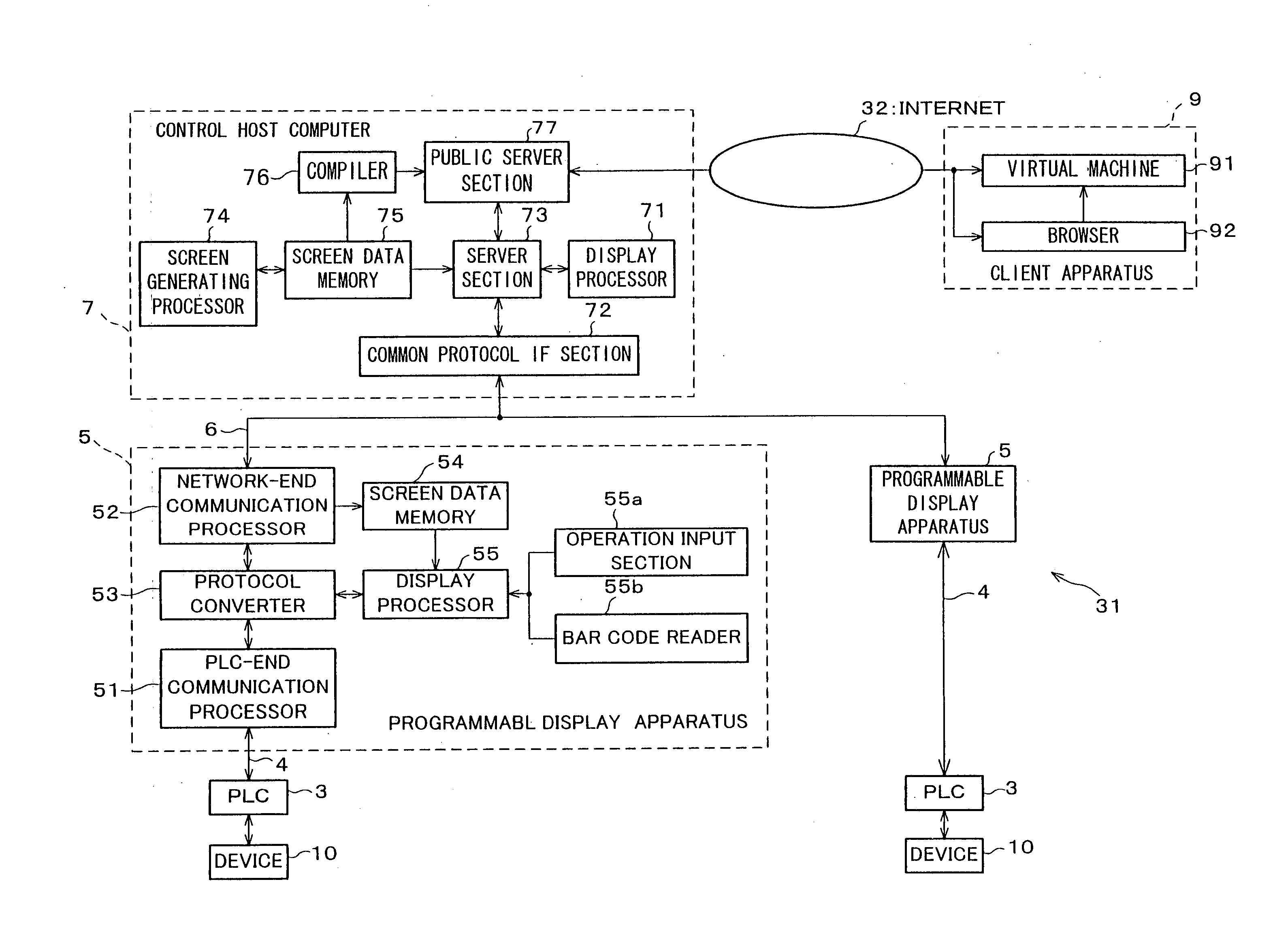
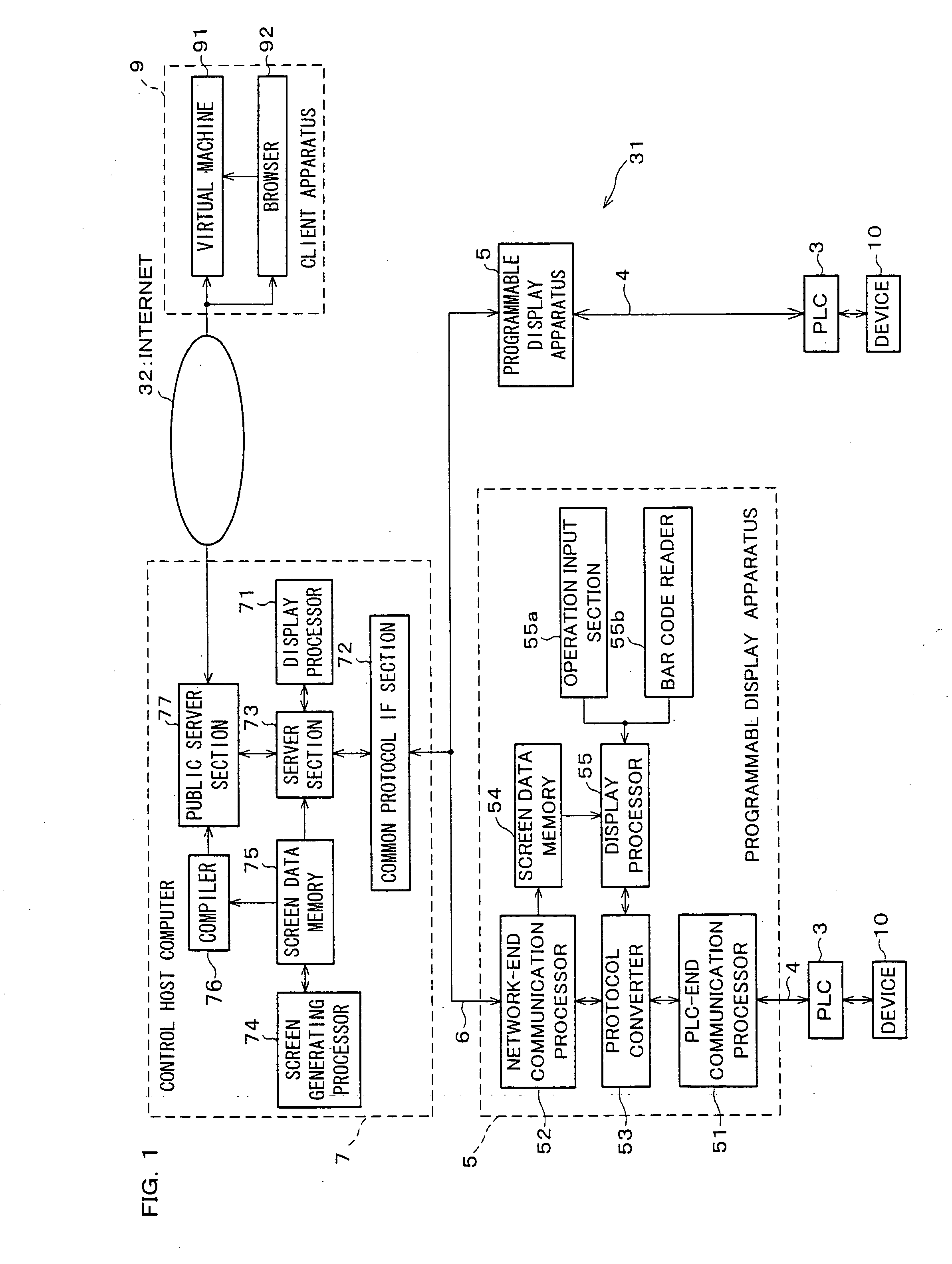
[0099] A control system according to the present embodiment shown in FIG. 1 is a system that is especially suitable for use in controlling a target system that is controlled by a plurality of PLCs, which work in combination, for example, in case where the target system is an automatic assembling machine of a belt conveyer type.
[0100] The present control system is provided with programmable logic controllers (PLCs) 3, programmable display apparatuses (hereinafter, just referred to as display apparatuses) 5, a network 6, a control host computer (hereinafter, just referred to as a control computer) 7, and a client apparatus (terminal apparatus) 9.
[0101] The PLCs 3, which are control apparatuses for controlling respective devices 10 that compose target systems in accordance with a control program stored in advance, are connected with the display apparatuses 5 via serial cables 4. The PLCs...
second embodiment
[0278] Described below is another embodiment of the present invention, with reference to FIGS. 31 to 37. Note that, in the present embodiment, constituent elements having the equivalent function as the constituent elements of the aforementioned first embodiment are labeled in the same manner and their explanations are omitted here.
[0279] A control system of the present embodiment is, as shown in FIG. 31, provided with a control host computer (hereinafter, just referred to as a control computer) 1, a plurality of display apparatuses 5, and a plurality of PLCs 3.
[0280] The control computer 1 and the display apparatuses 5 are connected to each other via a network 6, which allows communication in a common communication protocol. On the other hand, the display apparatuses 5 and PLCs 3 are respectively connected to each other via a serial cable 4, which allows communication in a specific communication protocol. Moreover, the display apparatuses 5 are connected to a computer 33 for gener...
third embodiment
[0355] Described below is yet another embodiment of the present invention with reference to FIGS. 38 to 43. Note that, in the present embodiment, constituent elements having the equivalent function as the constituent elements of the aforementioned first and second embodiments are labeled in the same manner and their explanations are omitted here.
[0356] A control system of the present embodiment is, as shown in FIG. 38, provided with a control host computer (hereinafter, denoted as a control computer) 2, a plurality of display apparatuses 5, a plurality of PLCs 3, and a client apparatus 9.
[0357] The control computer 2 and the display apparatuses 5 are connected with each other via a network 6 (common network), with which communication in a common protocol is possible. On the other hand, the display apparatuses 5 and PLCs 3 are respectively connected with each other via a serial cable 4 (designated network), with which communication in a specific communication protocol is possible. ...
PUM
Abstract
Screen data is generated by a screen generating processor (74) of a control host computer (7) and transmitted to a programmable display apparatus (5). In accordance with the screen data, the programmable display apparatus (5) inquires a PLC (3) or the like about a state of a device (21), so as to update the display or transmit a control instruction depending on an input result. On the other hand, a control host computer (7) has a public server section (77) to transmit to a client apparatus (9) via the Internet an applet, which is generated by a compiler (76) compiling the screen data. The client apparatus (9) executes the applet to transmit to the public server section (77) an or the control instruction inquiry similar to those the programmable display apparatus (5) makes. In this way, the display is updated in accordance with a response. This realizes a control system, which allows a display content of the programmable display apparatus (5) to be remotely checked from a remote area remote from the programmable display apparatus (5), without newly generating a display screen.
Description
TECHNICAL FIELD [0001] The present invention relates (a) to a control server and a control terminal for use in a control system having a programmable display apparatus, and for checking / controlling (checking and / or controlling) display contents of the programmable display apparatus from a remote location without generating a new display-use screen, (b) to the control system having those, and (c) to a control communication program for use in the control system. BACKGROUND ART [0002] Conventionally, industrial control apparatuses called as programmable logic controllers (hereinafter, just referred to as PLCs) have been widely used as control apparatuses for controlling various target systems, such as a belt conveyor-type automatic assembling machine, in order to realize various control, for example, sequence control. Furthermore, a use of the plural PLCs in combination has been applied in recent years, as the target system has become more complicated. [0003] Moreover, a display appara...
Claims
Application Information
Patent Timeline
Application Date:The date an application was filed.
Publication Date:The date a patent or application was officially published.
First Publication Date:The earliest publication date of a patent with the same application number.
Issue Date:Publication date of the patent grant document.
PCT Entry Date:The Entry date of PCT National Phase.
Estimated Expiry Date:The statutory expiry date of a patent right according to the Patent Law, and it is the longest term of protection that the patent right can achieve without the termination of the patent right due to other reasons(Term extension factor has been taken into account ).
Invalid Date:Actual expiry date is based on effective date or publication date of legal transaction data of invalid patent.

