Modular head lamination device and method

a lamination device and module head technology, applied in the direction of document inserters, paper hanging, manufacturing tools, etc., can solve problems such as production downtim

Active Publication Date: 2006-08-17
THE BOEING CO
View PDF19 Cites 104 Cited by
  • Summary
  • Abstract
  • Description
  • Claims
  • Application Information

AI Technical Summary

Benefits of technology

[0007] An embodiment of the present invention relates to a device to fabricate a composite item. The device includes and end effector and a positioning device. The end effector places a tow. The end effector includes a spindle, a tow path, and a compaction device. The spindle detachably secures a spool of tow and the path is disposed from the spool to the compaction device. The positioning device positions the end effector. The end effector is detachably secured to the positioning device.
[0008] Another embodiment of the present invention pertains to a system to fabricate a composite item. The system includes a tool, end effector, and positioning device. The tool includes a mandrel and a headstock. A tow is applied to the mandrel. The headstock rotates the mandrel about an axis. The end effector place the tow. The end effector includes a spindle, compaction device, and a path. The spindle detachably secures a spool of tow. The compaction device presses the tow upon the mandrel. The path is disposed from the spool to the compaction device. The positioning device operates cooperatively with the headstock to position the end effector relative to the tool and the end effector is detachably secured to the positioning device.
[0009] Yet another embodiment of the present invention relates to a method of fabricating a composite item. In this method, a first end effector is selected from a plurality of end effectors to apply a tow to a form. The first end effector is secured to a positioning device and the tow is applied to the form.

Problems solved by technology

In addition, resin often builds up on or around components that carry the tow from the creel to the head and can cause downtime in production.

Method used


Image

  • Modular head lamination device and method
  • Modular head lamination device and method
  • Modular head lamination device and method

Examples


Embodiment Construction

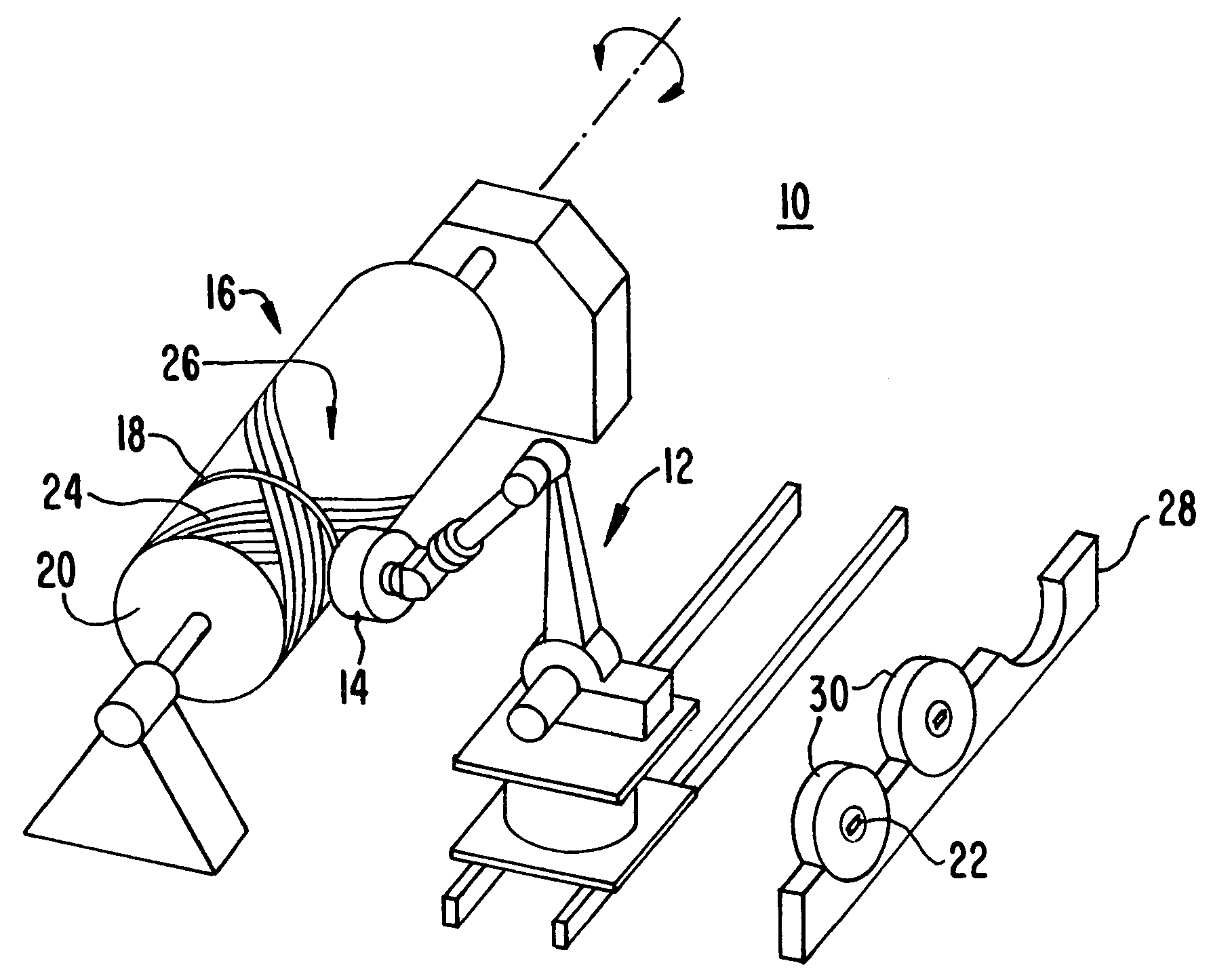
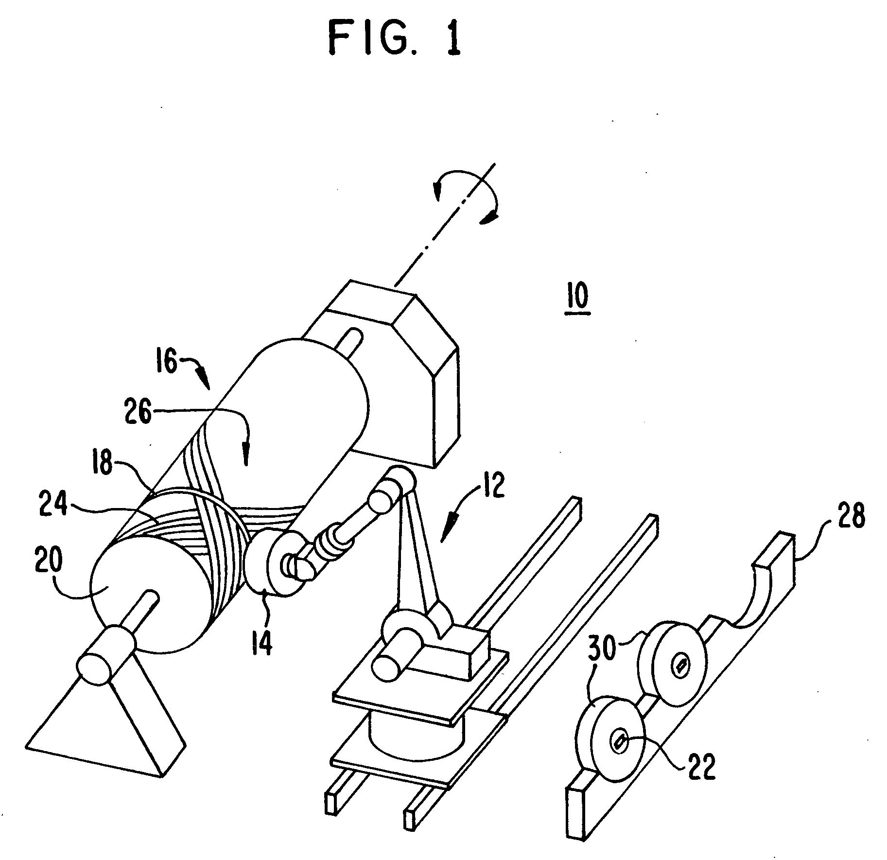
[0018] The invention will now be described with reference to the drawing figures, in which like reference numerals refer to like parts throughout. As shown in FIG. 1, a laminating device 10 suitable for use in an embodiment of the invention includes a positioning device 12 and an end effector 14. The positioning device 12 is configured to position or otherwise control the movement of the end effector 14. In an embodiment of the invention, the positioning device 12 is a robotic armature or gantry-type positioning device configured to control three to ten or more axes of movement. However, it is to be understood that the specific number of axes may depend upon the particular operating condition and thus, the number of axes controlled is not critical to the invention.

[0019] The laminating device 12 is configured to fabricate an item 16 by applying a course material 18 on a form 20. Typically, the item 16 is fabricated from multiple plies or layers of the course material 18. In various...


PUM

PropertyMeasurementUnit
structuresaaaaaaaaaa
movementaaaaaaaaaa
sizeaaaaaaaaaa

Abstract

A composite item is fabricated with a device. The device includes and end effector and a positioning device. The end effector places a tow. The end effector includes a spindle, compaction device, and a path. The spindle detachably secures a spool of tow and the path is disposed from the spool to the compaction device. The positioning device positions the end effector. The end effector is detachably secured to the positioning device.

Description

FIELD OF THE INVENTION [0001] The present invention generally relates to a lamination device. More particularly, the present invention pertains to a system and device for, and method of, fabricating a composite item. BACKGROUND OF THE INVENTION [0002] Composite items are typically constructed from layers of material that are laminated together. The categories of materials utilized to fabricate or ‘layup’ composite items includes, for example: fiber; fabric; tape; film; and foil. Within each of these categories, a multitude of diverse materials are utilized. For example, fibers utilized includes: glass; carbon; aramid; quartz; and the like. When these fibers are arranged as woven sheets and unidirectional ribbons, they are referred to as fabric and tape, respectively. [0003] Fiber placement is a process used to construct or fabricate composite items. These composite items include relatively simple planar sheets or panels to relatively large complex structures. The composite items are...

Claims


Application Information

Patent Timeline
Patent Type & Authority Applications(United States)
IPC IPC(8): B65H81/00
CPCB29C70/32B29C70/384B29C70/388Y10T156/1788Y10T156/1348Y10T483/17B29C70/545
Inventor KISCH, ROBERT A.KRAMP, ROBERT A.LUM, MATTHEW K.WAMPLER, ROBERT R.
Owner THE BOEING CO
Why Eureka
Try Eureka