
Two-step method of coating an article for security printing

a technology of security printing and two-step method, which is applied in the direction of electric/magnetic/electromagnetic heating, magnetic bodies, instruments, etc., can solve the problems of greater optical illusivity and more difficult counterfeiting

Active Publication Date: 2006-08-31
VIAVI SOLUTIONS INC
View PDF99 Cites 89 Cited by
  • Summary
  • Abstract
  • Description
  • Claims
  • Application Information

AI Technical Summary

Benefits of technology

[0016] It is an object of this invention to provide a more complex image having at least two distinct features wherein each feature is embodied in a separate coating and whe...

Problems solved by technology

Although these prior art references provide some useful and interesting optical effects, there is a need for patterns which have a greater degree of optical illusivity, and which are more difficult to counterfeit.

Method used


Image

  • Two-step method of coating an article for security printing
  • Two-step method of coating an article for security printing
  • Two-step method of coating an article for security printing

Examples


Embodiment Construction

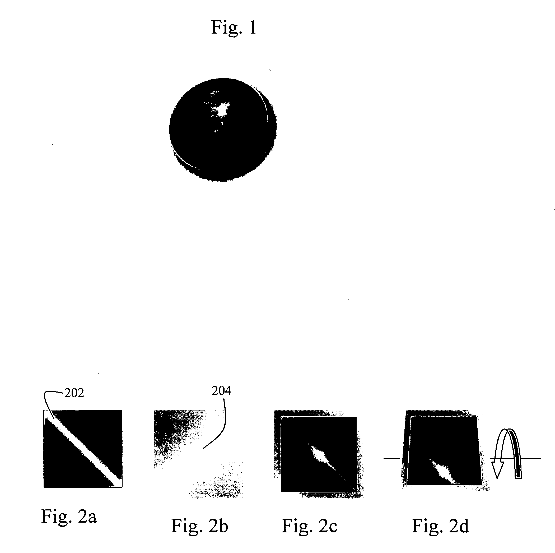
[0038] Orienting of magnetic flakes dispersed in a paint or an ink vehicle along lines of an applied magnetic field may produce a plurality of illusive optical effects. Many of these effects, described in other patents and patent applications assigned to Flex Products Inc., have dynamic animation-like appearance similar to holographic kinograms or a tiger eye effect in gemstones. When a graphic image, printed on the surface of a substrate in the presence of a magnetic field, is tilted or bent with respect to the light source and to the viewer, the illusive optical effect moves toward or out of the viewer, or to the left or to the right.

[0039] However, in accordance with this invention it is possible to fabricate very different and more complex kinds of optical effects with two-stage printing or painting of an article with magnetic ink or paint containing magnetic particles, in the presence of different magnetic fields. In the first stage the clear or dyed ink or paint vehicle, mixe...


PUM

PropertyMeasurementUnit
Coloraaaaaaaaaa
Concentrationaaaaaaaaaa
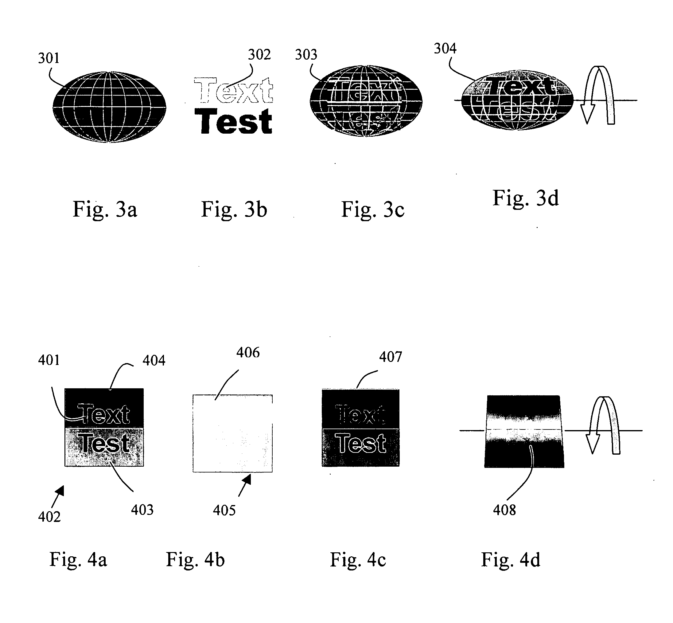
Magnetic fieldaaaaaaaaaa

Abstract

A two-step method of making of a security printed image is disclosed and includes coating of the surface of a substrate with a predetermined image shape with an ink containing flaked magnetic pigment in a predetermined concentration, exposing a wet printed image to a magnetic field to align magnetic particles in a predetermined manner, allowing the ink to cure, and coating the substrate with a second printed image on the top of the first image. The second printed image with the same or different image shape is printed with another ink containing clear or dyed ink vehicle mixed with flaked magnetic pigment in a low concentration, exposed to the magnetic field of the same or different configuration as the first printed image and cured until the ink is dry.

Description

CROSS-REFERENCE TO RELATED APPLICATIONS [0001] This application is a continuation-in-part of U.S. patent application Ser. No. 11 / 028,819 filed Jan. 4, 2005, which is a divisional of U.S. patent application Ser. No. 10 / 243,111 filed Sep. 13, 2002, now U.S. Pat. No. 6,902,807 of Jun. 7, 2005, which are incorporated herein by reference for all purposes. [0002] This invention claims priority from US Provisional patent application No. 60 / 700,994 filed Jul. 20, 2005, which is incorporated herein by reference for all purposes. [0003] This application is related to U.S. patent application Ser. No. 10 / 029,405, filed Dec. 20, 2001, now issued as U.S. Pat. No. 6,749,936 of Jun. 15, 2004; U.S. Ser. No. 09 / 919,346, filed Jul. 31, 2001, now issued as U.S. Pat. No. 6,692,830 of Feb. 17, 2004; and U.S. Ser. No. 10 / 117,307 filed Apr. 5, 2002, now issued as U.S. Pat. No. 6,841,238 of Jan. 11, 2005, which are incorporated herein by reference for all purposes.FIELD OF THE INVENTION [0004] This inventio...

Claims


Application Information

Patent Timeline
IPC IPC(8): B32B27/20
CPCB05D3/207B05D5/06B05D7/52B41M3/14Y10T428/25B42D2035/24G09F19/14B42D25/328B42D2033/16B42D25/369
Inventor RAKSHA, VLADIMIR P.COOMBS, PAUL G.TEITELBAUM, NEILMARKANTES, CHARLES T.ARGOITIA, ALBERTO
Owner VIAVI SOLUTIONS INC
Learn More