Optical network terminal with illegal transmission detection circuitry

Active Publication Date: 2006-09-07
TELLABS PETALUMA
View PDF5 Cites 51 Cited by
  • Summary
  • Abstract
  • Description
  • Claims
  • Application Information

AI Technical Summary

Problems solved by technology

The improper transmission detector to detect when the optical system is improperly transmitting, and assert the illegal transmission signal when the optical system is improperly transmitting.

Method used


Image

  • Optical network terminal with illegal transmission detection circuitry
  • Optical network terminal with illegal transmission detection circuitry
  • Optical network terminal with illegal transmission detection circuitry

Examples


Embodiment Construction

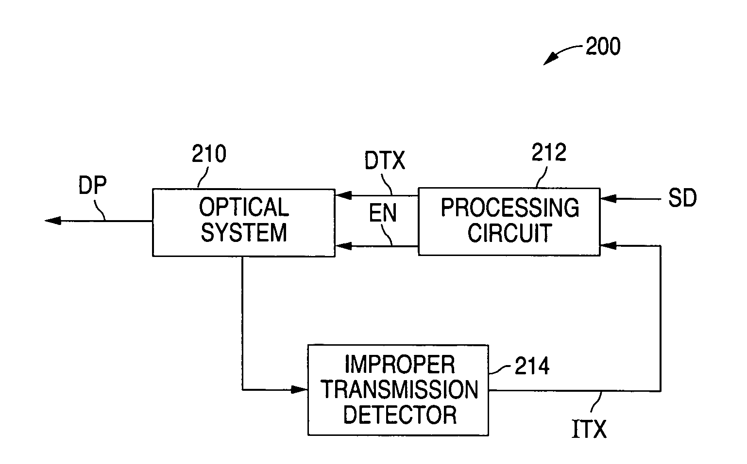
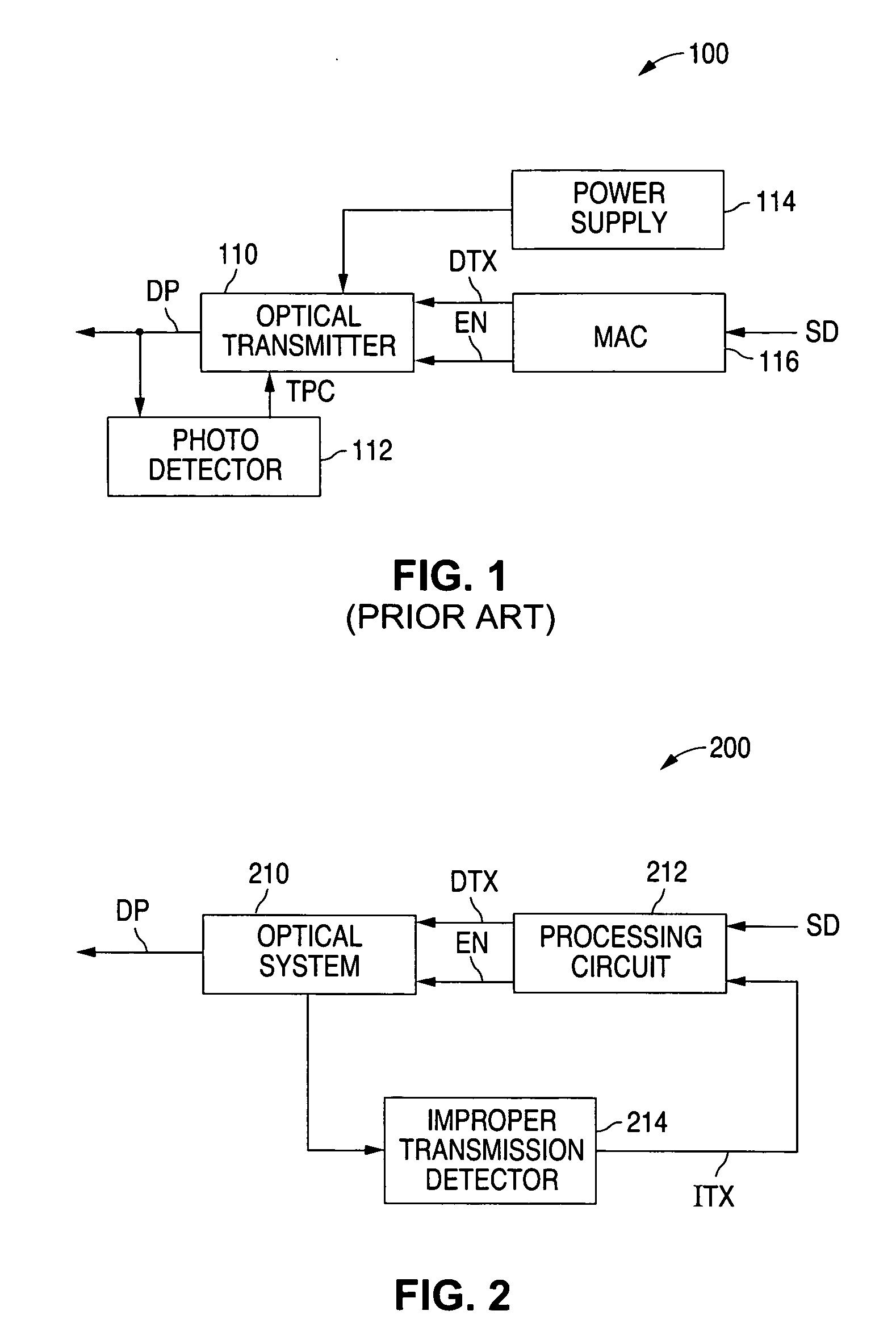
[0021]FIG. 2 shows a block diagram that illustrates an optical network terminal (ONT) 200 in accordance with the present invention. As described in greater detail below, ONT 200 monitors itself to determine when it is illegally transmitting and, when an illegal transmission is detected, turns itself off.

[0022] As shown in FIG. 2, ONT 200 includes an optical system 210 that generates and outputs an upstream data packet DP to an optical line terminal (OLT) via a splitter / combiner in response to an outgoing data packet DTX. Optical system 210 determines an output power level, and outputs the upstream data packet DP with the output power level in response to a transmit enable signal EN when optical system 210 receives power.

[0023] As further shown in FIG. 2, ONT 200 also includes a processing circuit 212 that generates the outgoing data packet DTX in response to incoming subscriber data SD, and the transmit enable signal EN when the upstream data packet DP is to be transmitted. In add...


PUM


Abstract

An optical network terminal, which includes an optical transmitter, monitors the status of the optical transmitter, such as the output or the power consumption of the optical transmitter, to determine when the optical transmitter is illegally transmitting. When an illegal transmission is detected, the optical network terminal removes power from the optical transmitter.

Description

BACKGROUND OF THE INVENTION [0001] 1. Field of the Invention [0002] The present invention relates to optical network terminals and, more particularly, to an optical network terminal with illegal transmission detection circuitry. [0003] 2. Description of the Related Art [0004] A fiber-to-the-x (FTTx) passive optical network (PON) is a point-to-multipoint communications network. Examples of an FTTx network include a fiber-to-the curb (FTTC) network and a fiber-to-the-home (FTTH) network. In an FTTx network, downstream data packets are transmitted from an optical line terminal (OLT) to a number of optical network terminals (ONT) that are located at or near a corresponding number of end users. Upstream data packets, on the other hand, are transmitted from the ONTs back to the OLT. [0005]FIG. 1 shows a block diagram that illustrates a prior-art example of an optical network terminal (ONT) 100. As shown in FIG. 1, ONT 100 includes an optical transmitter 110 that generates an upstream data...

Claims


Application Information

Patent Timeline
Patent Type & Authority Applications(United States)
IPC IPC(8): H04B10/08
CPCH04B10/0799
Inventor EMERY, CLAYTON J.JOERGER, RICHARD B.
Owner TELLABS PETALUMA
Why Eureka
Try Eureka