Phase locked loop comprising a sigma-delta modulator

a phase locked loop and modulator technology, applied in pulse automatic control, oscillator generators, pulse techniques, etc., can solve the problems of affecting the transmission speed of modulated data, and requiring large bandwidth for modern applications in communications technology. , to achieve the effect of reducing interference swing

a phase locked loop and modulator technology, applied in pulse automatic control, oscillator generators, pulse techniques, etc., can solve the problems of affecting the transmission speed of modulated data, and requiring large bandwidth for modern applications in communications technology. , to achieve the effect of reducing interference swing

US20060202768A1Inactive Publication Date: 2006-09-14INTEL CORP

Image

  • Phase locked loop comprising a sigma-delta modulator
  • Phase locked loop comprising a sigma-delta modulator
  • Phase locked loop comprising a sigma-delta modulator

Examples


Embodiment Construction

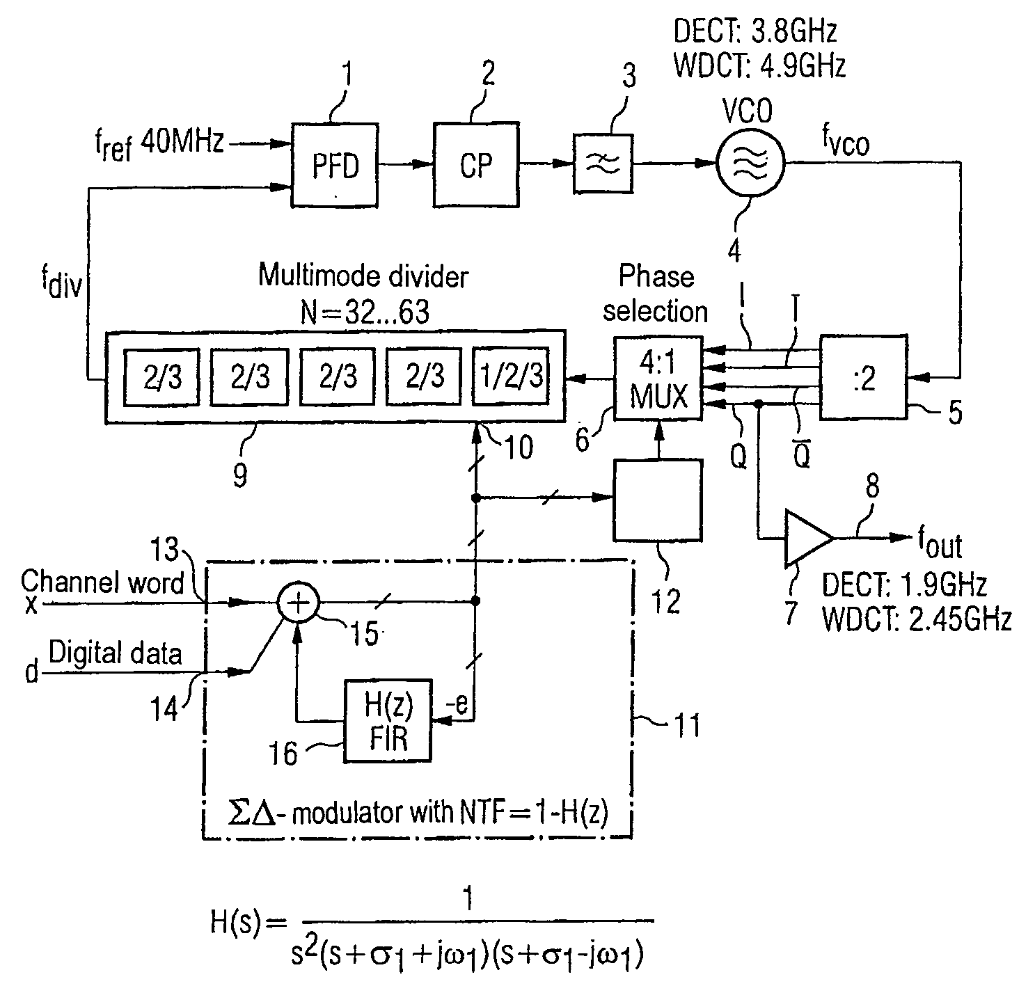
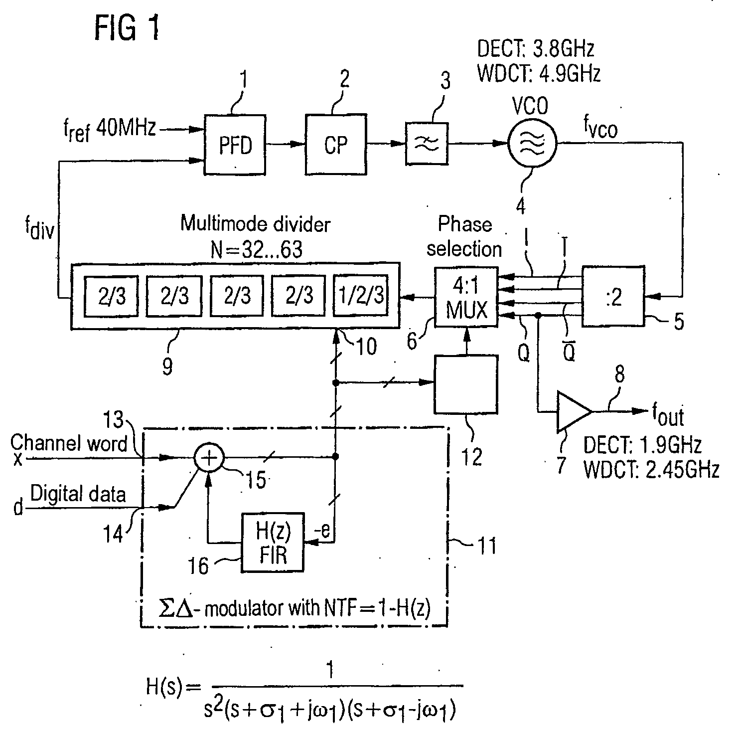
[0048]FIG. 1 shows a phase locked loop with a phase comparator 1 having two inputs and an output. One of the two inputs of the phase detector or phase comparator 1 can have a reference frequency generator (not shown here) connected to it which delivers a reference frequency Fref. The output of the phase detector 1 has a voltage controlled oscillator 4 connected to it via a charge pump circuit 2 and a loop filter 3, which is in the form of a low-pass filter and which is connected downstream of the charge pump circuit 2. The output of the oscillator 4 has a 4:1 multiplexer 6 connected to it via a :2 frequency divider 5. The :2 frequency divider 5 has four outputs at which it is possible to tap off the signal at the output frequency Fout of the phase locked loop in four different phases. One of the four outputs of the frequency divider 5 forms the output 8 of the phase locked loop via an amplifier 7.

[0049] The four outputs of the frequency divider 5 are connected to a respective assoc...


PUM


Abstract

The invention is directed to a phase locked loop with a ΣΔ modulator. A multimodulus divider in the feedback path of the PLL is actuated by the ΣΔ modulator. The latter has a design which can be described by a complex transfer function H(s) in the Laplace plane, said transfer function having a complex-conjugate pair of pole points. The arrangement allows a significant reduction in the noise in critical frequency domains and hence allows adherence to transmission masks based on radio specification even when the PLL bandwidth is as large as the modulation bandwidth.

Description

REFERENCE TO RELATED APPLICATIONS [0001] This application is a continuation of U.S. patent application Ser. No. 11 / 145,821, entitled “Phase-locked Loop Comprising a Sigma-Delta Modulator”, filed on Jun. 6, 2005, that is a continuation of PCT / DE03 / 03894, filed Nov. 25, 2003 which was not published in English, that claims the benefit of the priority date of German Patent Application No. DE 102 57 185.6, filed on Dec. 6, 2002, the contents of which both are herein incorporated by reference in their entireties.FIELD OF THE INVENTION [0002] The present invention relates to a phase locked loop with a ΣΔ (sigma-delta) modulator. BACKGROUND OF THE INVENTION [0003] A phase locked loop (PLL) of the generic type is specified in the printed document U.S. Pat. No. 6,008,703. This document describes a frequency synthesizer in which a ΣΔ PLL is used to produce a signal at a modulated carrier frequency. This phase locked loop, which is shown by way of example in FIG. 2A in the indicated prior art d...

Claims


Application Information

Patent Timeline
14 Sep 2006
Publication
US20060202768A1
IPC
H03L7/00; H03L7/081; H03L7/197
CPC
H03L7/081; H03L7/1976
Inventors
PUMA, GIUSEPPE LI; WAGNER, ELMAR