Method and device for driving solid electrolyte cells

Inactive Publication Date: 2006-09-14
INFINEON TECH AG
View PDF6 Cites 33 Cited by
  • Summary
  • Abstract
  • Description
  • Claims
  • Application Information

AI Technical Summary

Benefits of technology

[0018] It is an object of the present invention to design an electrical switching device based on CB cells in such a way that high current densitie

Problems solved by technology

Metallic ions are diffused from the anode material through the ion conductor, which generally exhibits poor electrical conductivity, by application of bipolar voltage pulses.
An essential disadvantage of conventional CB cells consists in the fact that, in particular during an erase operation, high voltages lead to high current densities and thus to the possibility of damage to the cell.
On the other hand, it is inexpedient to use low erase voltages since slow diffusion of the ions into the anode leads to a disadvantageous reduction of the switching speed.
A further essential disadvantage of the conventional method

Method used


Image

  • Method and device for driving solid electrolyte cells
  • Method and device for driving solid electrolyte cells
  • Method and device for driving solid electrolyte cells

Examples


Embodiment Construction

[0049] In the figures, identical reference symbols designate identical or functionally identical components or steps.

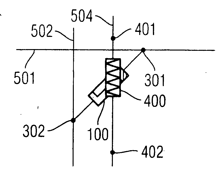
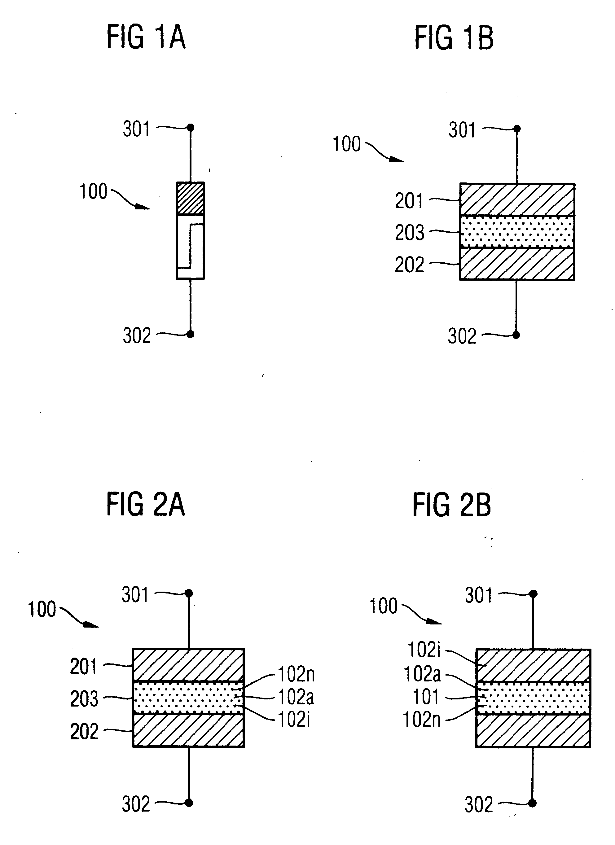
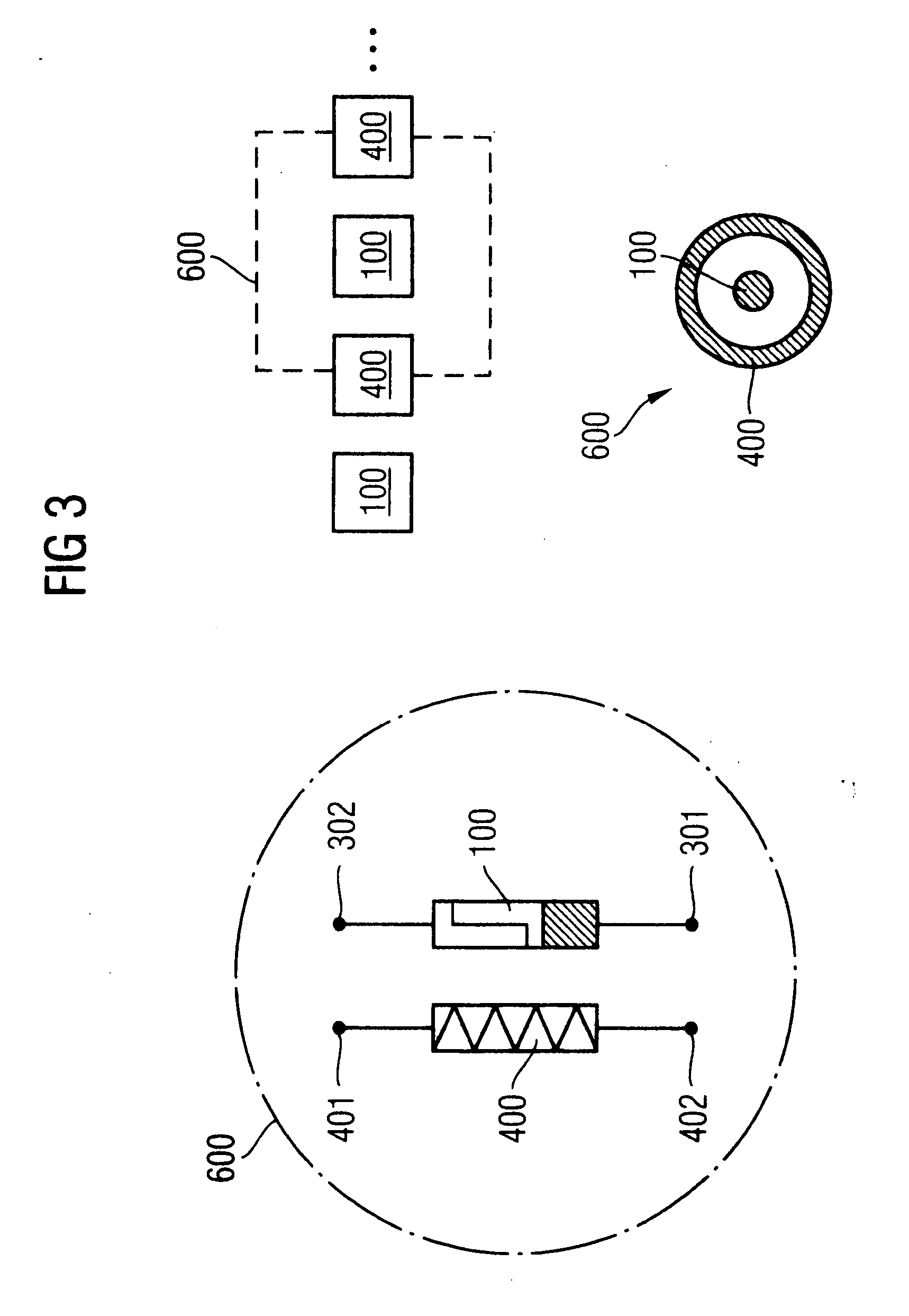
[0050] A TACB (thermally assisted conductive bridging) cell according to the invention is illustrated in FIGS. 1(a) and 1(b). In this case, such a TACB cell, which is designated hereinafter by the reference symbol 600, essentially has two terminal units, that is to say a first terminal unit 301 and a second terminal unit 302 for the switching element 100. While FIG. 1(a) shows a schematic circuit symbol of such a switching element 100, FIG. 1(b) schematically illustrates the construction of the switching element 100. The switching element 100 essentially comprises a first electrode unit 201 and a second electrode unit 202, the first electrode unit 201 being connected to the first switching terminal unit 301, while the second electrode unit 202 is connected to the second switching terminal unit 302.

[0051] As will be explained below with reference to FIG. 3, the elect...


PUM


Abstract

An electrical switching device comprises a switching element and a heating device for heating the switching element. The switching element comprises a first electrode, a second electrode, and an electrolyte layer arranged between and contact-connected to the first and second electrode. The switching element is configured to establish a conducting path between the first and second electrodes via the electrolyte layer by conduction elements having diffused from the first electrode into the electrolyte layer.

Description

BACKGROUND OF THE INVENTION [0001] 1. Field of the Invention [0002] The present invention relates generally to solid-electrolyte-based memory cells, and relates in particular to switching operations such as, for instance, an erasure and / or a setting (programming) of solid electrolyte cells, and to a switching device for carrying out the method. In particular, the present invention relates to a switching method for accelerating switching operations within a solid electrolyte of a memory cell. [0003] 2. Description of the Related Art [0004] The present invention specifically relates to an electrical switching device, in which an electrical through-switching is brought about by means of a conduction path being established in a switching element or in which an electrical switching-off is brought about by means of the conduction path being removed in the switching element. In this case, the switching element has a first electrode unit, a second electrode unit and an electrolyte layer arr...

Claims


Application Information

Patent Timeline
IPC IPC(8): H01G9/04
CPCG11C13/0011G11C13/0069G11C2013/008G11C2213/77G11C2213/79H01L27/2436H01L45/085H01L45/1286H01L45/142H01L45/143H01L45/146H10B63/30H10N70/245H10N70/8613H10N70/8822H10N70/8825H10N70/8833A47J31/106A47J31/4403
Inventor PINNOW, CAY-UWESYMANCZYK, RALF
Owner INFINEON TECH AG
Why Eureka
Try Eureka