Multicomponent marine geophysical data gathering system

a geophysical data and multi-component technology, applied in seismology, seismic data collection, seismic data collection in water-covered areas, etc., can solve the problems of reducing the utility of recorded data, difficult to record data outside a selected bandwidth without excessive attenuation or notches, and not being practical to tow cables deeper, so as to reduce the spectral notches

Inactive Publication Date: 2006-09-28
TENGHAMN STIG RUNE LENNART +2
View PDF27 Cites 22 Cited by
  • Summary
  • Abstract
  • Description
  • Claims
  • Application Information

AI Technical Summary

Problems solved by technology

Because of the ghost reflection, the water surface acts like a filter, making it difficult to record data outside a selected bandwidth without excessive attenuation or notches in the recorded data.
It has not been practical to tow cables deeper than about 9 meters because the location of the spectral notch in the frequency spectrum of the signal detected by a hydrophone substantially diminishes the utility of the recorded data.
It has also not been practical to tow cables at a depth shallower than about 6 meters, because the ghost signal reflected from the water surface substantially attenuates the signal detected by a hydrophone within the frequency band of interest.
Maintaining such orientation is non-trivial in a marine streamer and significantly more problematic than maintaining such orientation on the ocean bottom.
Nevertheless, no streamers containing both hydrophone and geophones are in commercial use.
In addition to the problem of maintaining orientation, severe noise from streamer cables has been considered prohibitive to use of particle velocity sensors in streamers.
Because the voltage output signal from particle velocity sensors is normally not as strong as the output signal from hydrophones, the noise level in streamer cables has been a detriment to the use of particle velocity sensors.
However, because of the variation in properties of the seafloor from location to location, impedance mismatch between the seafloor and the sensor and sensor housing can cause problems.
Such mismatch in impedance can cause various types of distortion in both the hydrophone signal and the geophone signal.

Method used


Image

  • Multicomponent marine geophysical data gathering system
  • Multicomponent marine geophysical data gathering system
  • Multicomponent marine geophysical data gathering system

Examples


Embodiment Construction

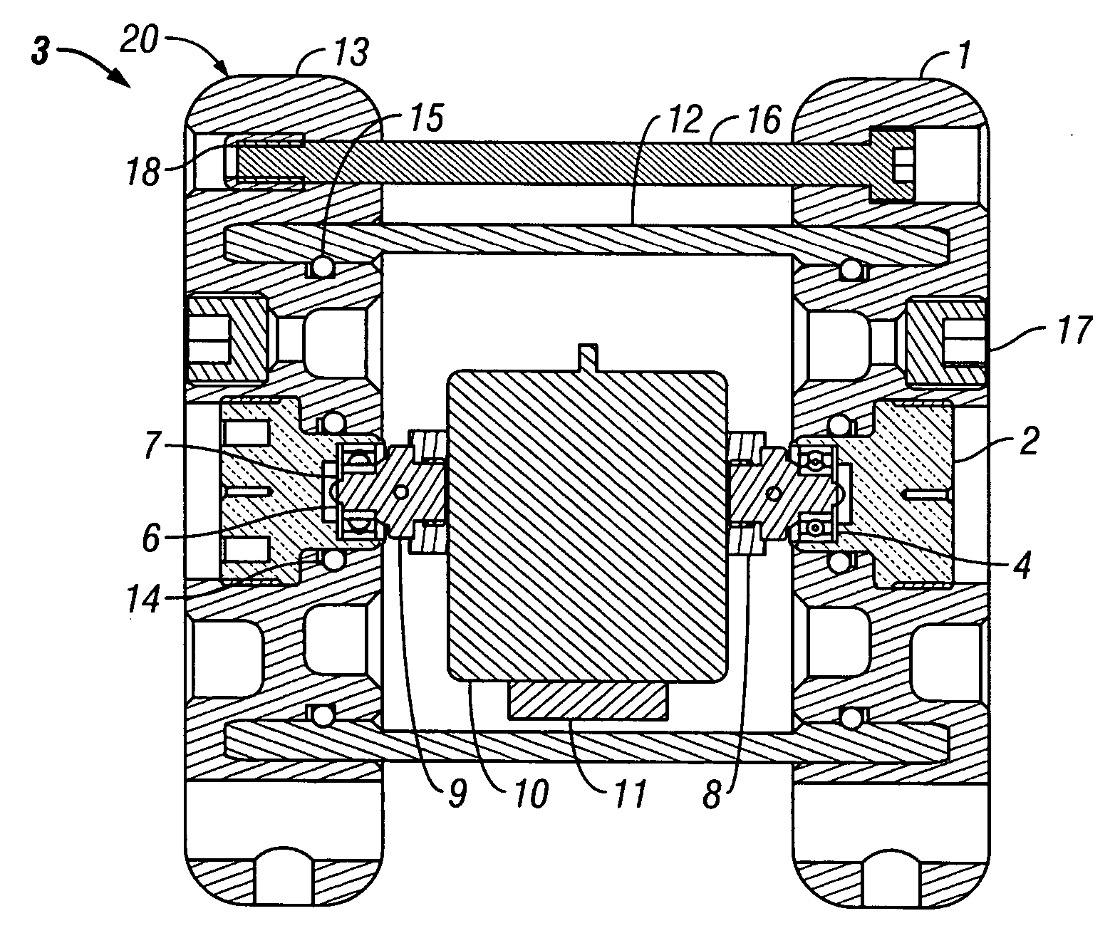
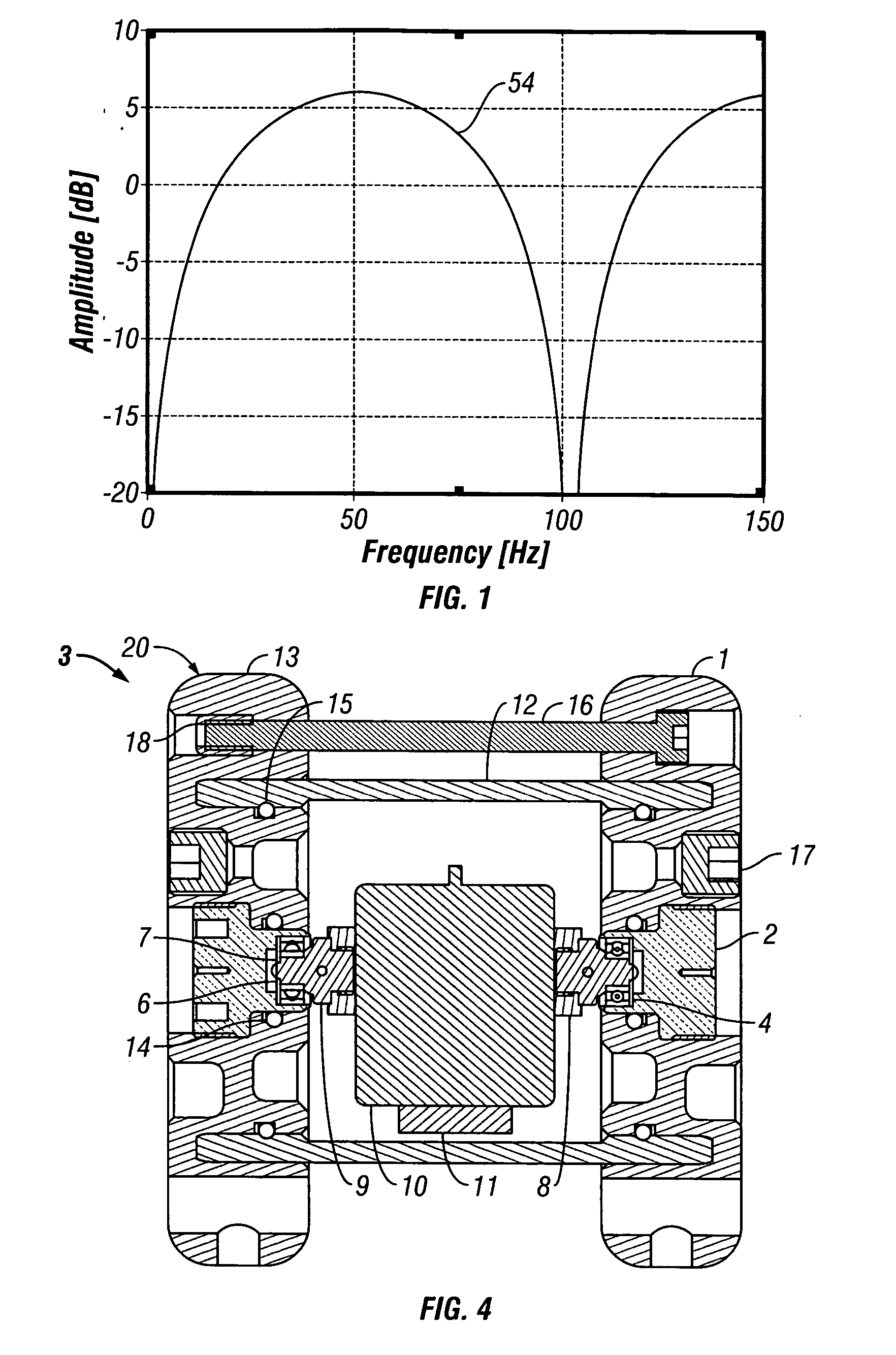
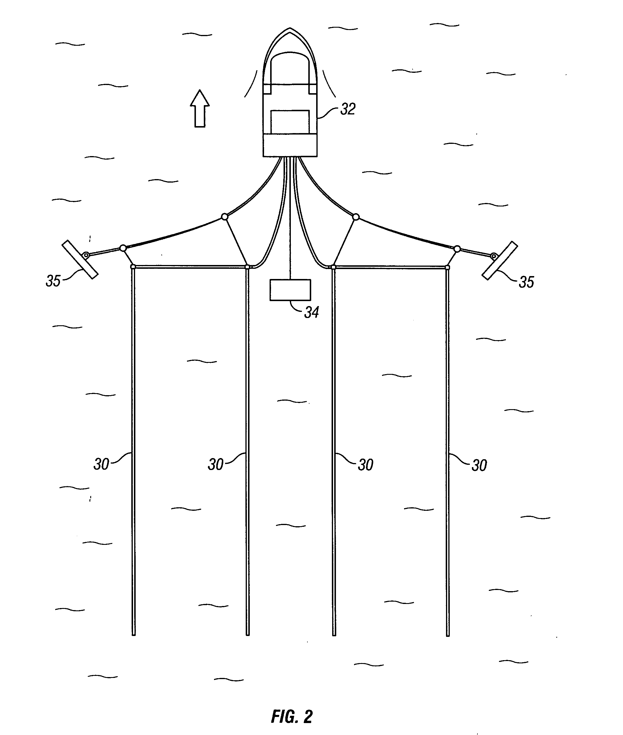
[0037]FIG. 2 illustrates a typical geophysical exploration configuration in which a plurality of streamer cables 30 are towed behind vessel 32. One or more seismic sources 34 are also normally towed behind the vessel. The seismic source, which typically is an airgun, but may also be a water gun or other type of source known to those of ordinary skill in the art, transmits seismic energy or waves into the earth and the waves are reflected back by reflectors in the earth and recorded by sensors in the streamers. Paravanes 35 are utilized to maintain the cables 30 in the desired lateral position. The invention may also be implemented, however, in seismic cables that are maintained at a substantially stationary position in a body of water, either floating at a selected depth or lying on the bottom of the body of water, in which case the source may be towed behind a vessel to generate shock waves at varying locations, or the source may also be maintained in a stationary position. Seismic...


PUM


Abstract

In one embodiment the invention comprises a particle velocity sensor that includes a housing with a geophone mounted in the housing. A fluid that substantially surrounds the geophone is included within the housing. The particle velocity sensor has an acoustic impedance within the range of about 750,000 Newton seconds per cubic meter (Ns / m3) to about 3,000,000 Newton seconds per cubic meter (Ns / m3). In another embodiment the invention comprises method of geophysical exploration in which a seismic signal is generated in a body of water and detected with a plurality of co-located particle velocity sensors and pressure gradient sensors positioned within a seismic cable. The output signal of either or both of the particle velocity sensors or the pressure gradient sensors is modified to substantially equalize the output signals from the particle velocity sensors and the pressure gradient sensors. The output signals from particle velocity sensors and pressure gradient sensors are then combined.

Description

CROSS-REFERENCE TO RELATED APPLICATIONS [0001] This application is a divisional application of, and claims priority from, U.S. Nonprovisional patent application Ser. No. 10 / 233266, filed on Aug. 30, 2002, the entirety of which is incorporated herein by reference.STATEMENT REGARDING FEDERALLY SPONSORED RESEARCH OR DEVELOPMENT [0002] Not applicable. BACKGROUND OF THE INVENTION [0003] 1. Field of the Invention [0004] The present invention is related to marine geophysical exploration. More specifically, the invention is related to sensors for detecting seismic signals and to marine seismic data gathering. [0005] 2. Description of Relevant Art [0006] In seismic exploration, geophysical data are obtained by applying acoustic energy to the earth at the surface and detecting seismic energy reflected from interfaces between different layers in subsurface formations. The seismic wave is reflected when there is a difference in impedance between the layer above the interface and the layer below...

Claims


Application Information

Patent Timeline
Patent Type & Authority Applications(United States)
IPC IPC(8): G01V1/38G01V1/18
CPCG01V1/181G01V1/185G01V1/189G01V1/3808G01V2210/56G01V1/18G01V1/28G01V1/36
Inventor TENGHAMN, STIG RUNE LENNARTSODAL, AUDUNSTENZEL, ANDRE
Owner TENGHAMN STIG RUNE LENNART
Why Eureka
Try Eureka