Thermosiphoning system with side mounted storage tanks

a technology of solar heaters and storage tanks, which is applied in solar heat systems, sustainable buildings, lighting and heating apparatus, etc., can solve the problems of system freezing in colder climates, and collectors with low thermal mass

Inactive Publication Date: 2006-10-05
FAFCO INC
View PDF99 Cites 16 Cited by
  • Summary
  • Abstract
  • Description
  • Claims
  • Application Information

AI Technical Summary

Benefits of technology

[0012] The invention relates in one embodiment to a thermosiphon solar heater. The thermosiphon solar heater includes an exposed substantially planar collector including a plurality of heat exchanger channels that are positioned next to one another in a parallel relationship. The thermosiphoning solar heater also includes a pair of exposed headers fluidly coupled to the collector. A first header is disposed at a top end of the collector. A second header is disposed at a bottom end of the collector. The thermosiphoning solar heater further includes one or more exposed storage tanks fluidly coupled to the header and positioned in a side by side relationship next to the collector.
[0013] The invention relates, in another embodiment, to a thermosiphoning solar heater. The thermosiphoning solar heater includes a flexible collector including a plurality of small diameter plastic tubes that are positioned side by side and held together with one or more clips. The thermosiphoning solar heater also includes a pair of rigid headers formed from large diameter plastic pipe. The headers are fluidly coupled and integrally formed with the tubes of the collector to form a single unified piece. A first header is perpendicularly positioned at a top end of the collector. A second header is perpendicularly positioned at a bottom end of the collector. The thermosiphoning solar heater further includes at least a first pair of rigid storage tanks formed from large diameter plastic pipe and in fluid communication with the headers. The storage tanks are positioned next to and parallel with the collector. A first storage tank is positioned on a first side of the collector. A second storage tank is positioned on a second side of the collector.

Problems solved by technology

Unfortunately, thermosiphon systems such as these suffer from several drawbacks.
For one, these systems can freeze in colder climates.
The collector typically has low thermal mass especially when compared to the storage tank and therefore the liquid contained therein is susceptible to freezing.
Unfortunately, these add complexity and cost to the system (which is supposed to be simple and economical).
For another, most thermosiphon systems are bulky devices formed from large, awkward and heavy parts and therefore they are difficult to manage and install.
Furthermore, because these systems are large and heavy, the costs of shipping these products are exorbitantly high.
In fact, in some cases, the cost of shipping may be higher than the cost of the product itself.
Another drawback with thermosiphon systems is that they tend not to be aesthetically pleasing.

Method used


Image

  • Thermosiphoning system with side mounted storage tanks
  • Thermosiphoning system with side mounted storage tanks
  • Thermosiphoning system with side mounted storage tanks

Examples


Embodiment Construction

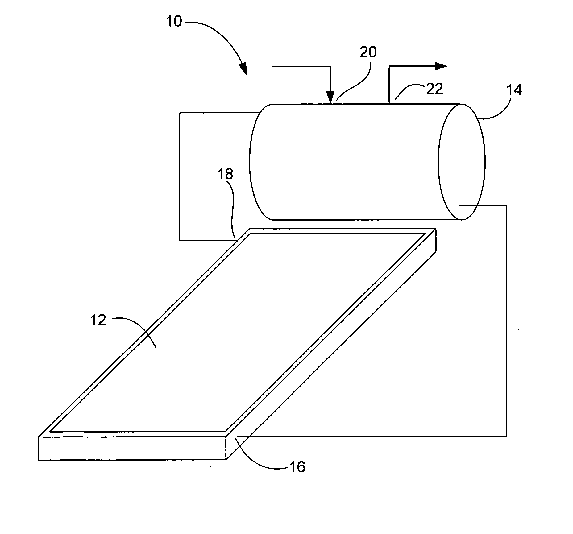
[0049] Most people skilled in the art believe that placing the storage tank above the collector is the only way to operate thermosiphoning systems. In fact, most people skilled in the art think that it is a critical to place the storage tank at least 18 inches above the collector to prevent reverse thermosiphing at night. This is reiterated throughout the solar literature. In contrast to this belief, the present invention proposes placing one or more storage tanks next to the collector rather than on top of the collector (e.g., side by side). By placing the storage tanks next to the collector, the system is capable of both forward and reverse thermosiphoning, i.e., the system forward thermosiphons when the water is being heated in the collector (during the day when the sun is shining) and reverse thermosiphons when the water is being cooled in the collector (at night when the sun is no longer shining).

[0050] One advantage having a system that reverse thermosiphons is that the colle...


PUM


Abstract

An improved thermosiphon solar heater is disclosed. The thermosiphon solar heater includes a substantially planar collector including a plurality of heat exchanger channels that are positioned next to one another in a parallel relationship. The thermosiphoning solar heater also includes a pair of headers fluidly coupled to the collector. A first header is disposed at a top end of the collector. A second header is disposed at a bottom end of the collector. The thermosiphoning solar heater further includes one or more exposed storage tanks fluidly coupled to the header and positioned in a side by side relationship next to the collector.

Description

BACKGROUND OF THE INVENTION [0001] 1. Field of the Invention [0002] The present invention relates generally to solar heaters. More particularly, the present invention relates to thermosiphoning solar heaters with side mounted storage tanks. [0003] 2. Description of the Related Art [0004] Solar heater systems are designed to capture heat from the sun and to store the solar heat until the heat is needed. In solar water heaters, the heat is ultimately transferred to water. Solar water heaters, which typically include a collector and storage tank, come in various forms including both active and passive systems. [0005] In active systems, the collector is typically a flat plate collector, which includes a rectangle box, tubes that extend through the box and a transparent cover that covers the box. The tubes help capture heat and transfer the heat to water inside the tubes. A pump is used to circulate water from a storage tank through the collector and back to the storage tank (typically l...

Claims


Application Information

Patent Timeline
Patent Type & Authority Applications(United States)
IPC IPC(8): F24J2/44
CPCF24J2/242F24J2/243Y02E10/44F24J2/4647Y02B10/20F24J2/44F24S10/72F24S80/30F24S90/10F24S10/73
Inventor BOWEN, GALENBOWEN, ROBERT
Owner FAFCO INC
Why Eureka
Try Eureka