Radio frequency identification tag package
a technology of radio frequency identification and package, applied in the field of packaging, can solve the problems of inability to communicate and the magnetic field does not reach the antenna, and achieve the effect of improving the efficiency of commodity distribution
- Summary
- Abstract
- Description
- Claims
- Application Information
AI Technical Summary
Benefits of technology
Problems solved by technology
Method used
Image
Examples
first embodiment
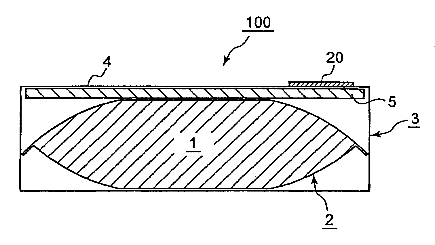
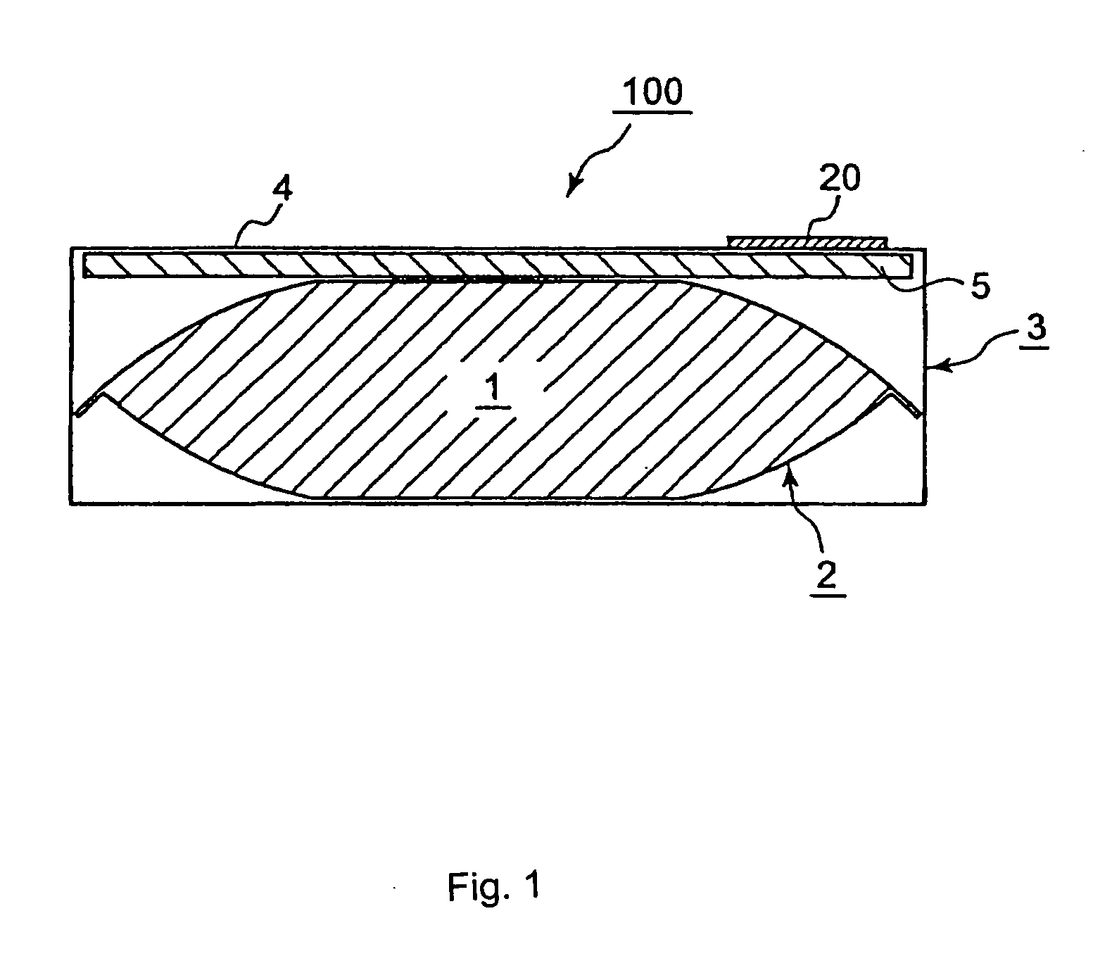
[0035]FIG. 1 is a cross-sectional view schematically showing a first embodiment of an RFID tag package according to the present invention.
[0036] An RFID tag package 100 according to the first embodiment includes a casing 3 having a quadrilateral vertical cross section, an RFID tag 20 attached to a part of the outer surface of the casing 3, and an inner bag 2 packaged in the casing 3 with an article 1 being airtightly packed therein. In the RFID tag package 100, a plate-shaped spacing member 5 (spacing means) having a specific thickness is inserted between the inner bag 2 and a face plate 4 of the casing 3 to which the RFID tag 20 is attached.
[0037] The inner bag 2 is formed by a stacked film including metal foil or a metal deposited layer containing aluminum, copper, or the like. This also applies to RFID tag packages shown in FIGS. 3 to 5 described later.
[0038] As the spacing member 5, corrugated cardboard having a specific thickness and having an air layer formed by wave-shaped...
second embodiment
[0044]FIG. 3 is a cross-sectional view schematically showing a second embodiment of the RFID tag package according to the present invention.
[0045] In each embodiment described below, sections functioning in the same manner as in the first embodiment are indicated by the same symbols. These sections are appropriately omitted in the description and the drawings.
[0046] An RFID tag package 200 according to the second embodiment differs from the RFID tag package 100 according to the first embodiment shown in FIG. 1 in that the size of the spacing member 5 inserted between the inner bag 2 and the face plate 4 of the casing 3 to which the RFID tag 20 is attached is reduced to such an extent that the inner surface of the face plate 4 can be covered at least in the area in which the RFID tag 20 is attached, and that the spacing member 5 is attached to the inner surface of the face plate 4 using an adhesive in the area in which the RFID tag 20 is attached to the outer surface.
[0047] The sp...
third embodiment
[0049]FIG. 4 is a cross-sectional view schematically showing a third embodiment of the RFID tag package according to the present invention.
[0050] In an RFID tag package 300 according to the third embodiment, the RFID tag 20 is attached to a part of the outer surface of the casing 3. A partition plate 6 (spacing means) is obliquely provided in the casing 3 to divide the casing 3 into a first portion in which the RFID tag 20 is attached to the outer surface and a second portion in which the RFID tag 20 is not attached. In the RFID tag package 300, the inner bag 2 is placed in the second portion in which the RFID tag 20 is not attached.
[0051] The partition plate 6 includes an adhesive portion 7a only on one end. The adhesive portion 7a is bonded to the inner surface of the upper face plate 4 to which the RFID tag 20 is attached on the outer surface. The other end of the partition plate 6 is not bonded to the inner surface of the casing 3. The partition plate 6 is formed to have such ...
PUM
 Abstract
Description
Claims
Application Information
 - R&D
- Intellectual Property
- Life Sciences
- Materials
- Tech Scout
- Unparalleled Data Quality
- Higher Quality Content
- 60% Fewer Hallucinations
Browse by: Latest US Patents, China's latest patents, Technical Efficacy Thesaurus, Application Domain, Technology Topic, Popular Technical Reports.
© 2025 PatSnap. All rights reserved.Legal|Privacy policy|Modern Slavery Act Transparency Statement|Sitemap|About US| Contact US: help@patsnap.com


