Linear measurement machine-readable medium, method and system

a machine-readable medium and linear measurement technology, applied in the field of linear measurement system, can solve problems such as inability to draw, out of date, graphic artists may bear any loss due to discrepancy,

Inactive Publication Date: 2006-10-05
CARLSON ERIC A
View PDF13 Cites 24 Cited by
  • Summary
  • Abstract
  • Description
  • Claims
  • Application Information

AI Technical Summary

Benefits of technology

[0012] Briefly stated, in accordance with an embodiment of the present invention, linear measurements are made of items by selecting a field of view including the items. A reference marker having a predetermined length, e.g., a yardstick or meter stick, is placed in the field of view. A digital image of the field of view is generated and stored, for example in a digital camera. Digital information indicative of the image may be sent over a network for processing or transported physically to a workstation in a medium. A user may view the image on a display. A program is provided in which the reference marker is resolved in the image, and an electronic length, e.g., a number of pixels between th

Problems solved by technology

The drawings may be unavailable or they may be out of date.
Commonly, if there is a discrepancy between the drawings and actual bus dimensions, the graphic artist will bear any loss due to the discrepancy.
It is not practical to measure every nook and cranny of a bus.
Having to take further measurements costs both time and money.
Exposures to hazards, if any, during measurement must be risked an additional time.
Such apparatus does not meet the needs of users such as those described above.
The complexity of such apparatus does not lend itself to low-cost manufacture or ease

Method used


Image

  • Linear measurement machine-readable medium, method and system
  • Linear measurement machine-readable medium, method and system
  • Linear measurement machine-readable medium, method and system

Examples


Embodiment Construction

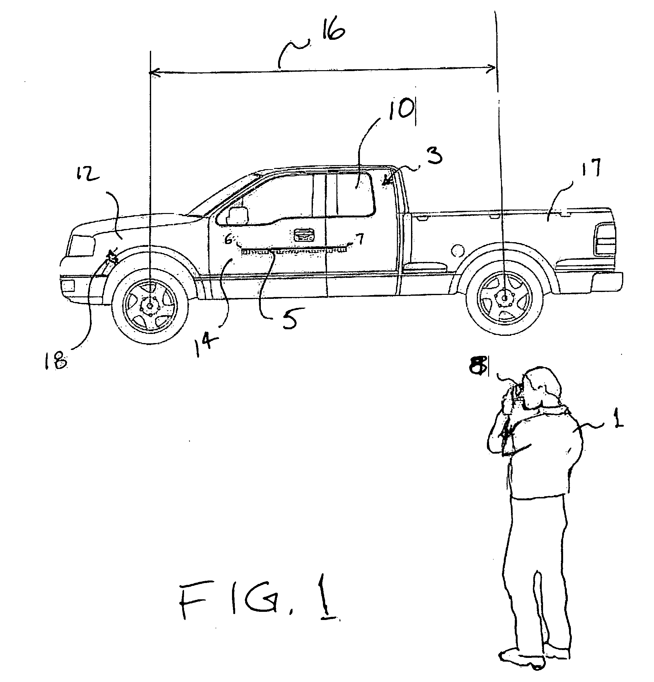
[0021]FIG. 1 is a perspective view of an embodiment of the present invention interacting in an operational environment. In the present illustration, a field user 1 is measuring dimensions of an object 3. The field user 1 will provide data to a base user 4 (FIG. 5) who will derive desired measurements from collected data. The field user 1 may be the same person as the base user. The base user 4 is generally a person who must have first hand knowledge of the characteristics and who is unable or unwilling, whether for reasons of reliability or regulation to accept a list of measurements made by others or is a person who is required to provide the service of taking measurements. Currently, it is customary for real estate agents, insurance adjusters, appraisers or other base users to leave their offices to go to the site of the object 3 and take their own measurements. It is noteworthy that embodiments of the present invention allow the base user 4 to have another person to collect data ...


PUM


Abstract

Linear measurements of items are made by selecting a field of view including the items. A reference marker of known length is placed in the field of view. A digital image of which is taken and stored. Digital image information is processed by a program, and with the reference marker is resolved in the image. A user may locate a cursor at an end of the reference marker and click to register the position. An electronic distance, e.g., a number of pixels between the ends of the reference marker, is normalized to the length of the reference marker. A user selects points on the image on a display to define a line segment on a dimension of interest to be determined. Calculations relate the length of the line segment to the length of the reference marker. A number indicated the desired dimension may be displayed on the image.

Description

CROSS REFERENCE TO RELATED APPLICATIONS [0001] The present application claims priority of U.S. Provisional Patent Application Ser. No. 60 / 667,235 filed Apr. 4, 2005, which is incorporated by reference herein in its entirety.FIELD OF THE INVENTION [0002] The present subject matter relates generally to a linear measurement system to replace measuring with a tape measure or the like in a which a field of view is established and measurements are made on an image comprehending the field of view. BACKGROUND OF THE INVENTION [0003] An important use of linear measuring is the measurement of objects surrounding us in our daily lives. These objects may include buildings, other structures, vehicles and subunits and components thereof. A new and expanding area requiring measurement has been enabled by the advent of large scale graphics. Signs and surfaces for wrapping objects are being produced in sizes that are unprecedented. One new form of large scale graphics is called the digital wrap. A s...

Claims


Application Information

Patent Timeline
IPC IPC(8): G06K9/36
CPCG06T7/60
Inventor CARLSON, ERIC A.
Owner CARLSON ERIC A
Why Eureka
Try Eureka