Connector assembling construction

a technology of connecting parts and connectors, applied in the direction of coupling device connection, coupling parts engagement/disengagement, incorrect coupling prevention, etc., can solve the problems of reducing assembly efficiency and difficult to miniaturize the entire connector

Inactive Publication Date: 2006-10-12
SUMITOMO WIRING SYST LTD
View PDF10 Cites 0 Cited by
  • Summary
  • Abstract
  • Description
  • Claims
  • Application Information

AI Technical Summary

Benefits of technology

[0013] Guiding projections of the first connector preferably are insertable into substantially conforming guiding grooves in the second connector when the two connectors are oriented properly. Thus, an erroneous insertion of the first connector, such as an upside-down insertion, can be avoided.

Problems solved by technology

However, connecting parts of the connectors are hidden between the module and the body and may be displaced from each other during the assembly process.
As a result, assembly efficiency may be reduced.
Thus, an attempt to miniaturize the guide restricts the correcting displacement, and it is difficult to miniaturize the entire connector.

Method used


Image

  • Connector assembling construction
  • Connector assembling construction
  • Connector assembling construction

Examples


Embodiment Construction

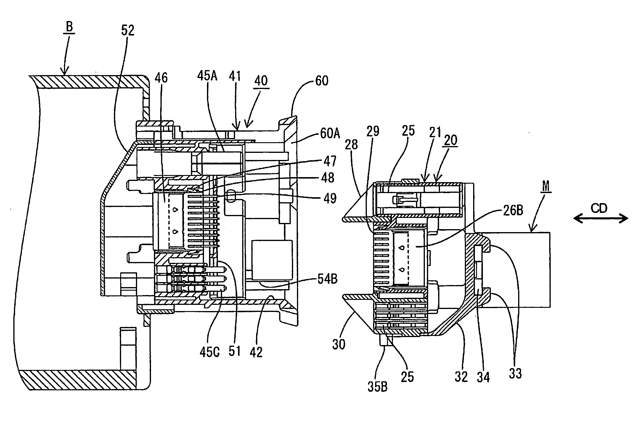
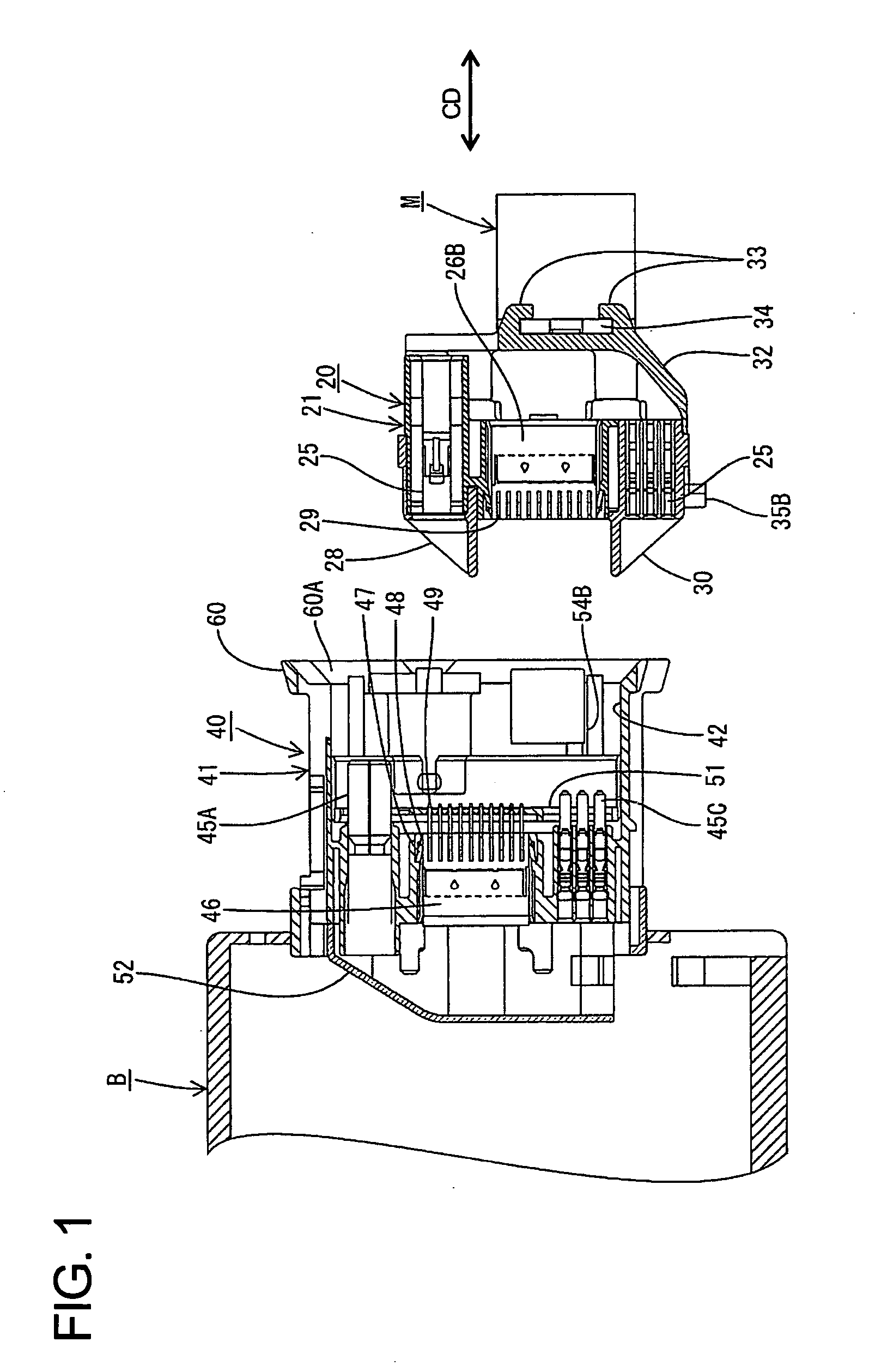
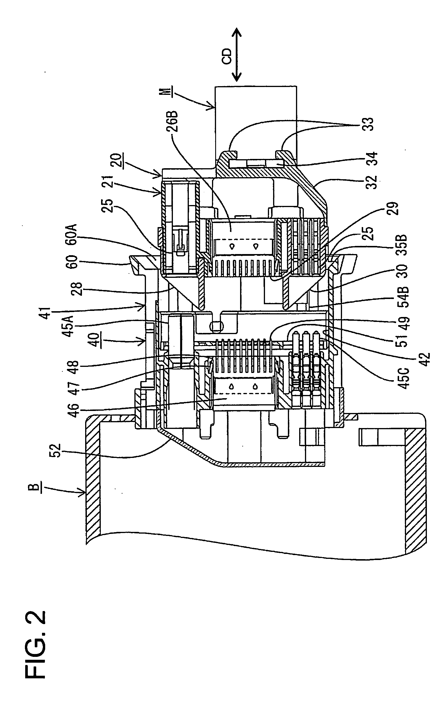
[0026] A movable connector according to the invention is identified by the numeral 20 in FIGS. 1 to 9. The movable connector 20 is provided on a module M, such as an instrument panel of an automotive vehicle, and is connectable with a waiting-side connector 40 on a body B as the module M is assembled with the body B. The waiting-side connector 40 is assembled with the body B to be substantially two-dimensionally movable in a mounting plane that is normal to a connecting direction CD of the two connectors 20, 40. In the following description, ends of connectors to be connected are referred to as the front ends, and reference is made to FIGS. 6 and 9 concerning vertical direction VD (height direction HD) and transverse direction TD (width direction WD).

[0027] The waiting-side connector 40 has a male frame 41 made e.g. of a synthetic resin. The male frame 41 is a wide block, and a receptacle 42 extends into the front end of the male frame 41. A guide 60 is formed at the front edge of ...


PUM


Abstract

A connector assembling construction includes a movable connector (20) provided on a module (M) such as an instrument panel of an automotive vehicle and a waiting-side connector (40) provided on a body (B) and having a receptacle (41) for receiving the movable connector (20). The movable connector (20) and the waiting-side connector (40) are connected as the module (M) is assembled with the body (B). Rib-shaped slanted surfaces (28, 30) project within the entire width range and within the entire height range of a connecting surface of the movable connector (20). The slanted surfaces (28, 30) are arranged at positions near opposing ends of the connecting surface, and have gradients to increase projecting amounts thereof as they extend in from the ends of the connecting surface.

Description

BACKGROUND OF THE INVENTION [0001] 1. Field of the Invention [0002] The invention relates to a connector assembling construction for connecting a module-side connector and a body-side connector as a module such as an instrument panel is assembled with a body in an automotive vehicle. [0003] 2. Description of the Related Art [0004] Modules, such as an instrument panel, must be assembled with the body of an automotive vehicle. The module and the body have connectors that must be connected with one another as the module and the body are assembled. However, connecting parts of the connectors are hidden between the module and the body and may be displaced from each other during the assembly process. As a result, assembly efficiency may be reduced. U.S. Pat. No. 6,878,001 discloses a connector assembling construction which is designed in view of this problem. The connector assembling construction of U.S. Pat. No. 6,878,001 has a waiting-side connector with a receptacle and a tapered guide...

Claims


Application Information

Patent Timeline
Patent Type & Authority Applications(United States)
IPC IPC(8): H01R13/62
CPCH01R13/64H01R13/631
Inventor ISHIKAWA, RYOTARO
Owner SUMITOMO WIRING SYST LTD
Why Eureka
Try Eureka