Connector with enhanced mounting process

a technology of connecting rods and mounting holes, applied in the direction of fastening means, sheet joining, snap-action fasteners, etc., can solve the problem that the sequence associated with said connectors involves the risk of assembly errors, and achieve the effect of preventing assembly errors

Active Publication Date: 2019-05-09
ILLINOIS TOOL WORKS INC
View PDF10 Cites 8 Cited by
  • Summary
  • Abstract
  • Description
  • Claims
  • Application Information

AI Technical Summary

Benefits of technology

[0037]In the case of a further assembly according to the invention, it is provided that the connector has, on a radial outer wall of the crossbar, a radial projection or a radial recess, and that the aperture in the first component has a corresponding radial recess or a corresponding radial projection such that the angular positions at which the crossbar is insertable into the aperture of the first component are limited to at maximum two angular positions, preferably one angular position. This prevents erroneous insertion.

Problems solved by technology

The inventors have found it disadvantageous that the assembly sequence associated with said connectors involves the risk of erroneous assembly.

Method used


Image

  • Connector with enhanced mounting process
  • Connector with enhanced mounting process
  • Connector with enhanced mounting process

Examples


Embodiment Construction

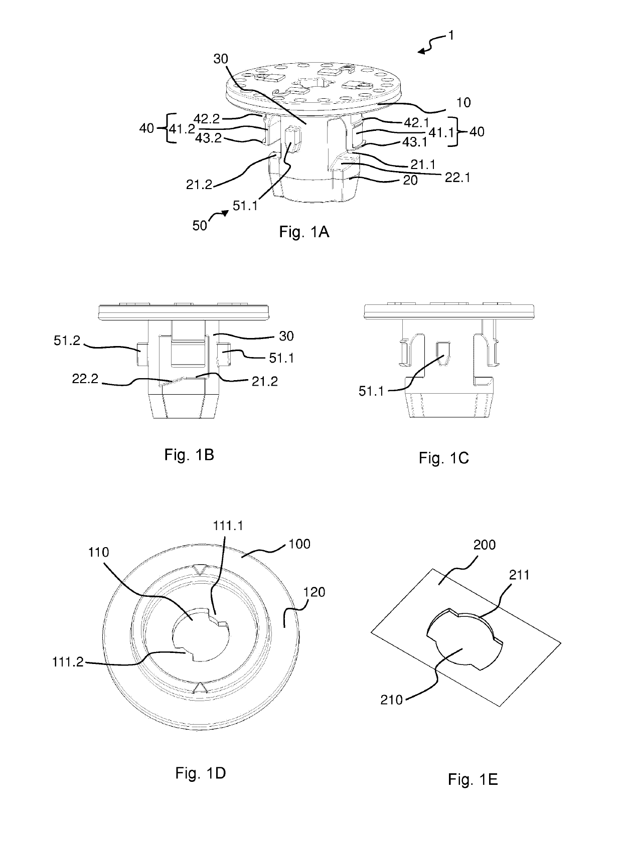
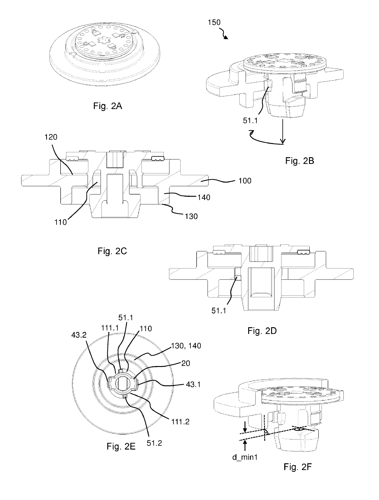
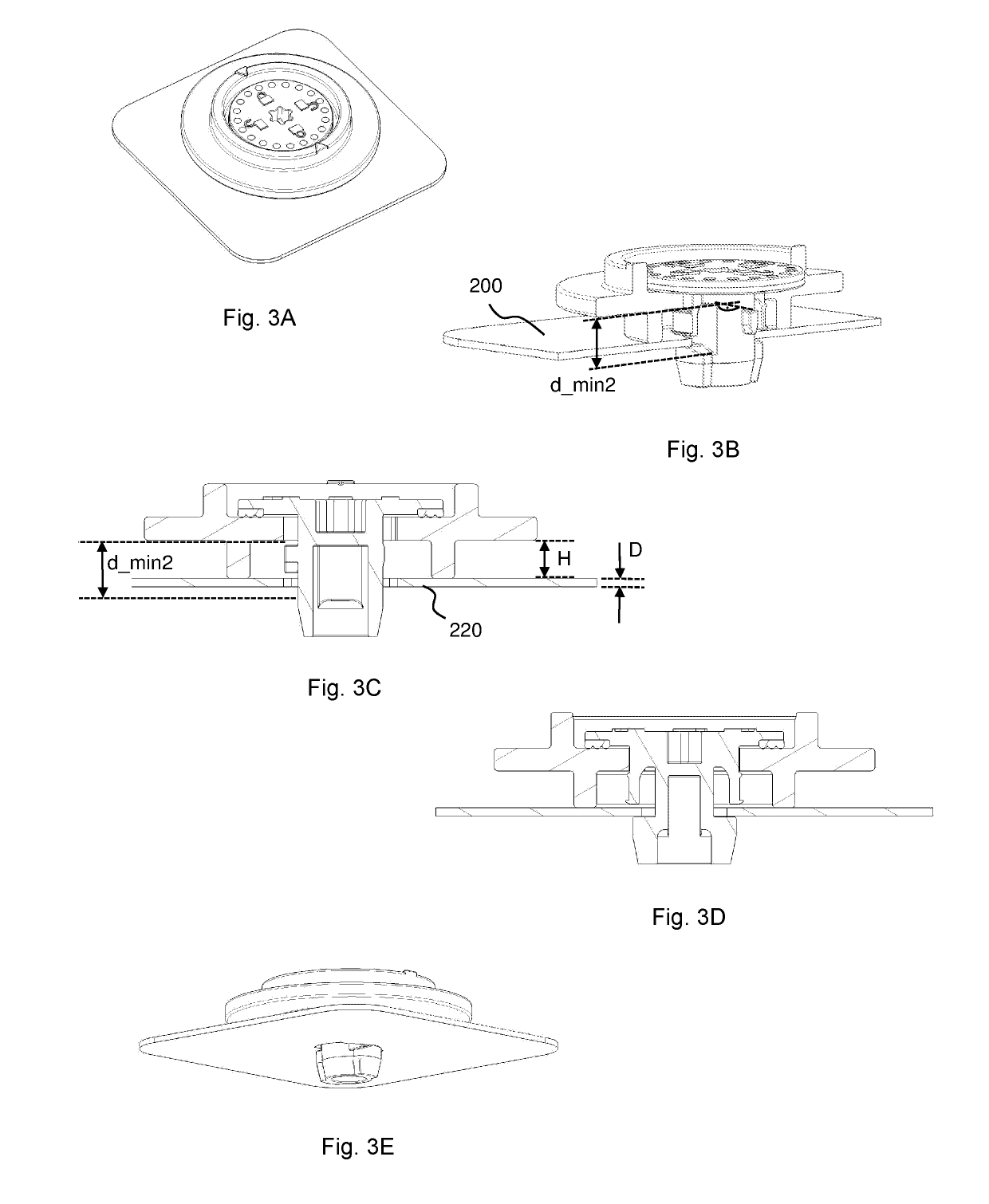
[0048]FIGS. 1A-1C show a connector according to the invention in a perspective view (FIG. 1A) and side views each offset by 90° (FIGS. 1B, 1C). The configuration is such that the connector 1 is configured to fasten a first component 100, here a door module, to a second component 200, here a door, of a motor vehicle, wherein the connector 1 has[0049]a bearing collar 10 for bearing against an upper side 120 of the first component 100,[0050]a crossbar 20 having one or more upper bearing surfaces 21.1, 21.2 for bearing against a lower side 220 of the second component 200 and for bracing the second component 200 against a lower bearing surface 130 of the first component 100 in a rotated final assembly position,[0051]a shaft portion 30 which supports the crossbar 20 and is oriented in the axial direction, for passing through corresponding apertures 110, 210 in the components 100, 200, and[0052]fastening means 40 for fastening the connector 1 to the first component 100 in a preassembly pos...


PUM


Abstract

A connector (1) for fastening a first component (100) to a second component (200) of a motor vehicle, includes a bearing collar (10) for bearing against the first component (100), a crossbar (20) having one or more upper bearing surfaces (21.1, 21.2) for bearing against the second component (200) and for bracing the second component (200) against the first component (100) in a rotated final assembly position, a shaft portion (30) for passing through corresponding apertures (110, 210) in the components (100, 200), and fastening means (40) for fastening the connector (1) to the first component (100) in a preassembly position. A rotation-blocking device (50) is configured to block rotation of the connector (1) in relation to the first component (100) in the preassembly position and only to release said rotation when the connector (1) has moved from the preassembly position in the direction of the final assembly position.

Description

TECHNICAL FIELD[0001]The invention relates in general to connectors.BACKGROUND[0002]The prior art U.S. Pat. No. 3,480,311, WO 2008 / 101531 A1 and U.S. Pat. No. 5,123,795—in each case disclose a connector for mechanically connecting at least two components, having a bearing collar and a crossbar and means for fastening to one of the components in a defined preassembly position.[0003]The inventors have found it disadvantageous that the assembly sequence associated with said connectors involves the risk of erroneous assembly.SUMMARY[0004]The object on which the invention is based was to improve the above-noted disadvantage. The object is achieved by the invention, in particular as defined in the independent claims.[0005]In particular, this object is achieved by a connector, wherein the connector is configured to fasten a first component, preferably a door module, to a second component, preferably a door, of a motor vehicle, wherein the connector has[0006]a bearing collar for bearing aga...

Claims


Application Information

Patent Timeline
Patent Type & Authority Applications(United States)
IPC IPC(8): F16B21/02F16B21/08
CPCF16B21/02F16B21/086F16B5/0621F16B5/065F16B5/0664F16B21/04
Inventor LEIDIG, CHRISTOPHMULLER, JAN
Owner ILLINOIS TOOL WORKS INC
Why Eureka
Try Eureka