Reproducing device
a technology of a recording device and a cartridge holder, which is applied in the direction of recording information storage, instruments, carrier constructional parts disposition, etc., can solve the problems that the recording-recording device not provided with the cartridge holder cannot provide the effect of naturally preventing and the following two points become the most problematic, so as to prevent the erroneous insertion of the cartridge holder and prevent the damage to the optical disk
- Summary
- Abstract
- Description
- Claims
- Application Information
AI Technical Summary
Benefits of technology
Problems solved by technology
Method used
Image
Examples
first embodiment
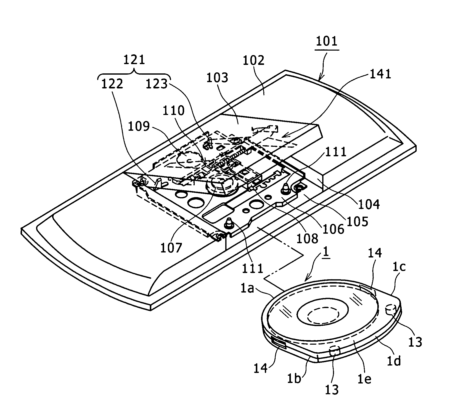
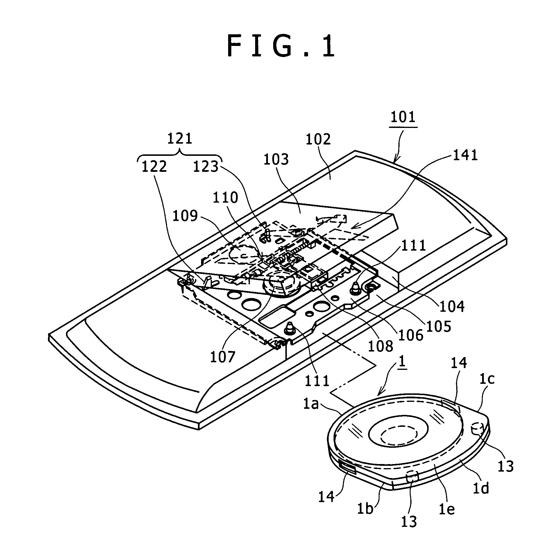
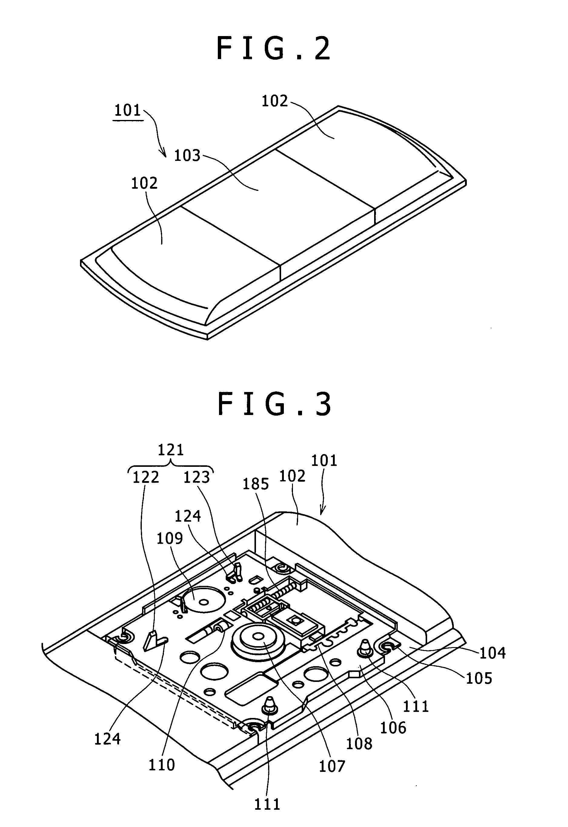
[0078]The erroneous insertion-preventing portion 121 shown in FIGS. 1 through 14 is formed by disposing a pair of left and right positioning projections 122, 123 at respective positions following (conforming to) the shape of the front surface 1a of the recording medium cartridge 1. The positioning projections 122, 123 are adapted to temporarily position the front surface 1a of the cartridge 1.
[0079]The first and second positioning projections 122, 123 are formed integrally with the chassis 106 by outsert molding. A placement reference surface 124 is provided at a base portion of each of the first and second positioning projections 122, 123 so as to position the cartridge 1 in the height direction thereof.
[0080]If the cartridge 1 is inserted in a normal posture, the front surface 1a of the cartridge 1 comes into contact with the first and second positioning projections 122, 123 to temporarily position the cartridge 1. As shown in FIG. 11, the tip of the positioning reference pin 111...
second embodiment
[0086]As described above, the erroneous insertion-preventing portion 121A of the second embodiment is configured such that the front surface 1a of the cartridge 1 is abutted against the curved surface 132 formed to follow (conform to) the shape of the front surface 1a. Thus, as shown in FIG. 18, when the cartridge 1 is inserted in a normal posture to abut the front surface 1a against the curved portion 132, both are brought into close contact with each other to temporarily position the cartridge 1.
[0087]If the cartridge 1 is about to be loaded back to front, a large gap 6 is defined between the curved portion 132 and the rear surface 1d of the cartridge 1 as shown in FIG. 19, which makes the wrong loading direction clear. Since the other configurations, functions and effects are the same as those of the first embodiment, duplicate explanations are omitted. Incidentally, the second embodiment is configured such that the erroneous insertion-preventing portion 121A is formed like the s...
PUM
| Property | Measurement | Unit |
|---|---|---|
| shape | aaaaa | aaaaa |
| time | aaaaa | aaaaa |
| angle | aaaaa | aaaaa |
Abstract
Description
Claims
Application Information
 - R&D
- Intellectual Property
- Life Sciences
- Materials
- Tech Scout
- Unparalleled Data Quality
- Higher Quality Content
- 60% Fewer Hallucinations
Browse by: Latest US Patents, China's latest patents, Technical Efficacy Thesaurus, Application Domain, Technology Topic, Popular Technical Reports.
© 2025 PatSnap. All rights reserved.Legal|Privacy policy|Modern Slavery Act Transparency Statement|Sitemap|About US| Contact US: help@patsnap.com


