
Channel estimation using a minimized channel prediction interval

a channel estimation and channel prediction technology, applied in the direction of transmission path division, baseband system details, wireless communication, etc., can solve the problems of reducing the quality of the resulting channel estimation, and reducing the relevance of channel estimation

Active Publication Date: 2006-10-19
MOTOROLA SOLUTIONS INC
View PDF6 Cites 15 Cited by
  • Summary
  • Abstract
  • Description
  • Claims
  • Application Information

AI Technical Summary

Problems solved by technology

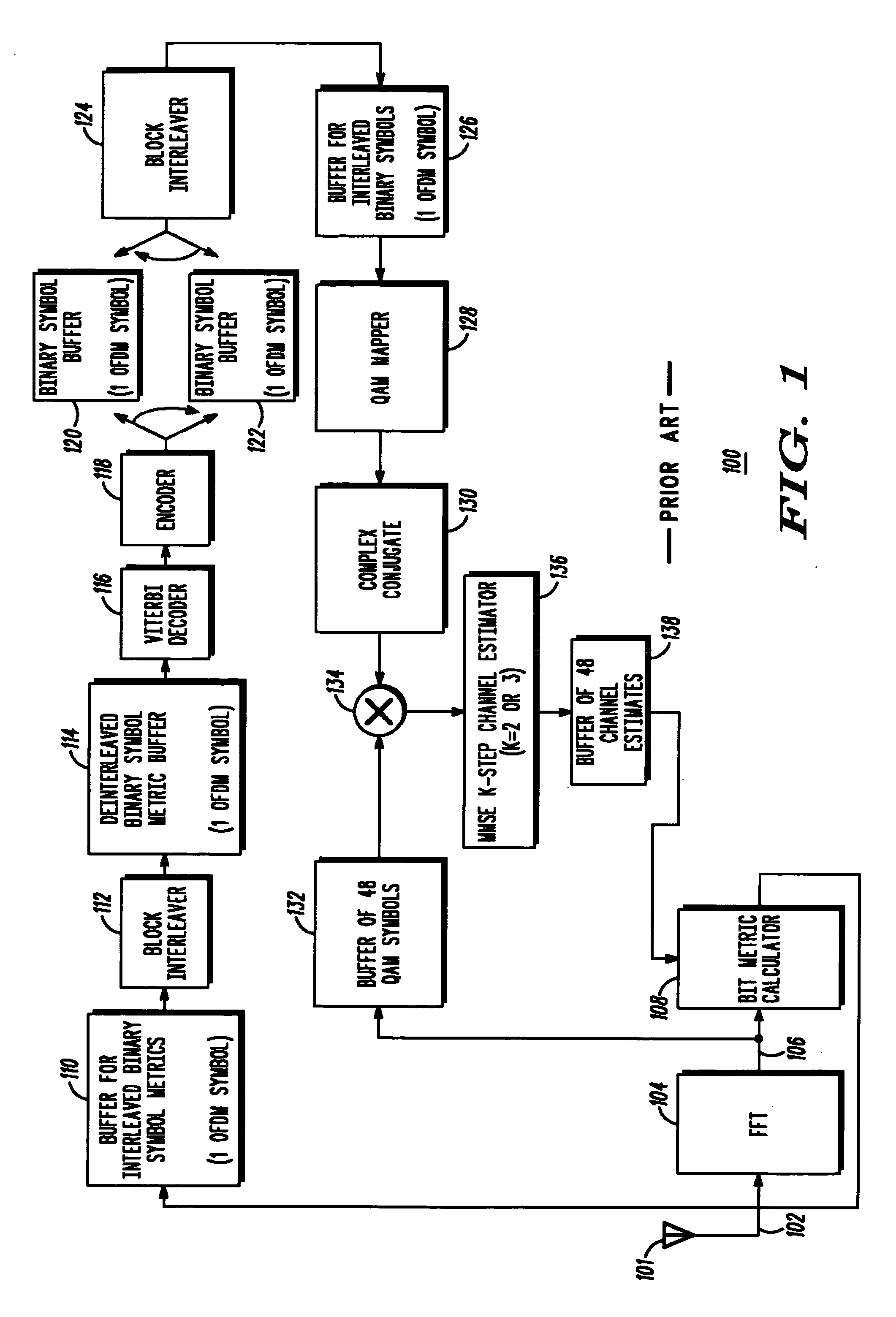
However, when such systems are operated at higher speeds, a strictly pilot symbol aided channel estimation methodology often proves inadequate.
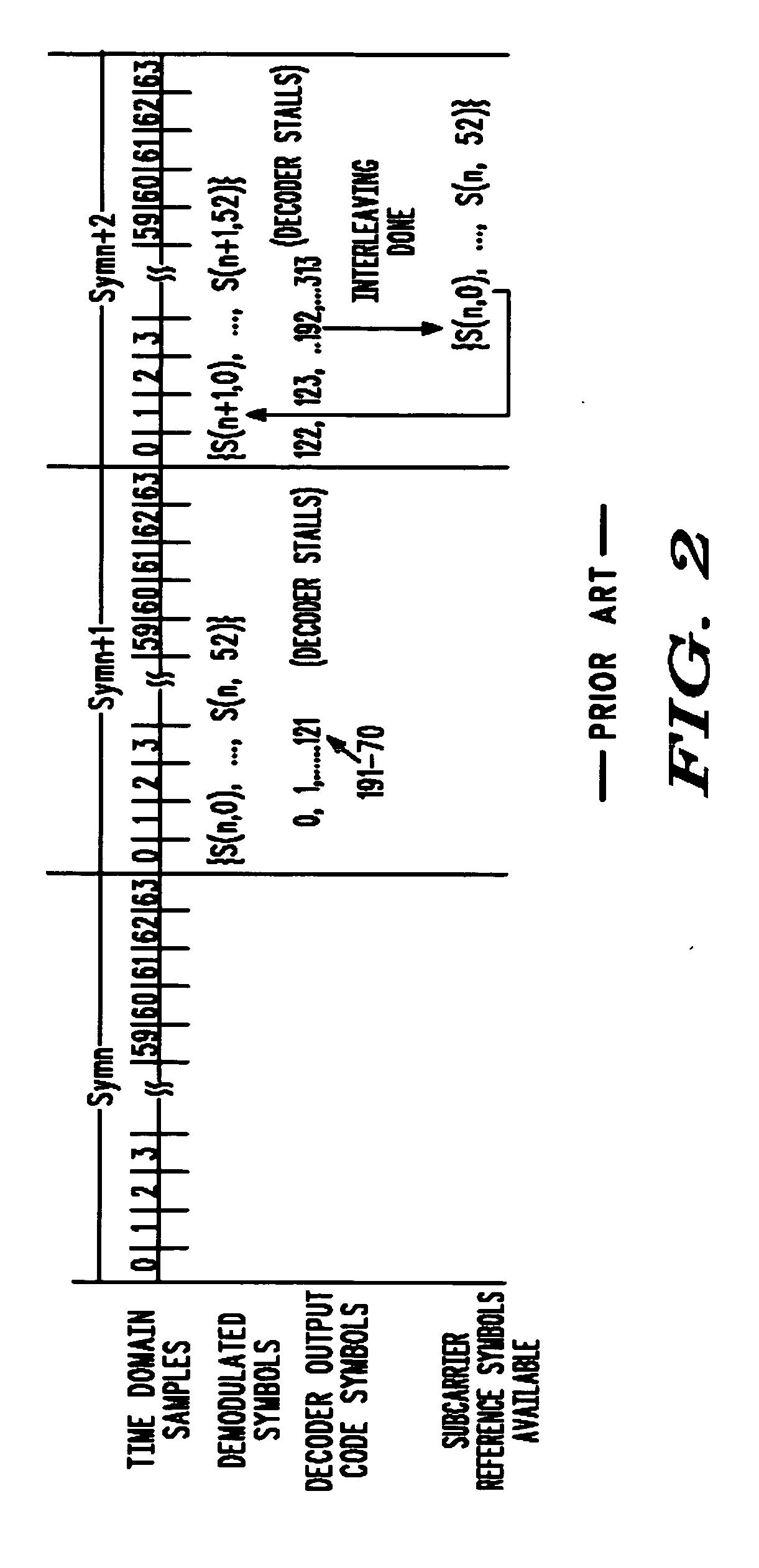
Thus, any increase in the delay associated with symbol regeneration and the resulting channel estimation will reduce the relevance of the channel estimation relative to the time that it is used.
As the delay increases, the prediction interval used by the channel estimator increases, and the quality of the resulting channel estimation is decreased.

Method used


Image

  • Channel estimation using a minimized channel prediction interval
  • Channel estimation using a minimized channel prediction interval
  • Channel estimation using a minimized channel prediction interval

Examples


Embodiment Construction

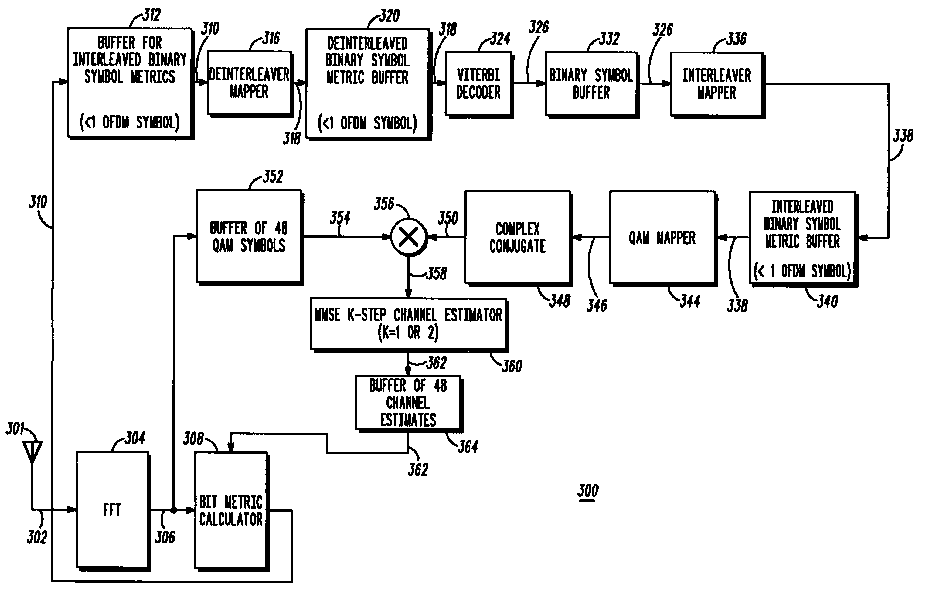
[0019] While this invention is susceptible of embodiments in many different forms, there are shown in the figures and will herein be described in detail specific embodiments, with the understanding that the present disclosure is to be considered as an example of the principles of the invention and not intended to limit the invention to the specific embodiments shown and described. Further, the terms and words used herein are not to be considered limiting, but rather merely descriptive. It will also be appreciated that for simplicity and clarity of illustration, common and well-understood elements that are useful or necessary in a commercially feasible embodiment may not be depicted in order to facilitate a less obstructed view of these various embodiments. Also, elements shown in the figures have not necessarily been drawn to scale. For example, the dimensions of some of the elements are exaggerated relative to each other. Further, where considered appropriate, reference numerals ha...


PUM


Abstract

A receiver configured for: a) receiving (410) a first OFDM symbol and generating a plurality of demodulated symbols for the first OFDM symbol; b) generating (420) decoder output code symbols corresponding to a subset of the plurality of demodulated symbols; c) determining (430) that a set of the decoder output code symbols make up a set of reference symbols corresponding to at least a portion of the subset of the plurality of demodulated symbols; d) generating (440) the set of reference symbols; e) generating (450) a set of channel estimates based on the set of reference symbols and the at least a portion of the subset of the plurality of demodulated symbols, for use in decoding a current OFDM symbol; and f) repeating steps b-e until a channel estimate for each demodulated symbol corresponding to the first OFDM symbol has been generated.

Description

FIELD OF THE INVENTION [0001] The present invention relates generally to decision-directed channel estimation in a receiver apparatus and more specifically to methods and apparatus for minimizing the channel prediction interval used to generate channel estimates. BACKGROUND OF THE INVENTION [0002] Pilot symbol aided Minimum Mean-Squared Error (MMSE) channel estimation (which uses only pre-determined or known symbols, commonly referred to in the art as pilot and preamble symbols, in deriving channel estimates) is a well-known method of obtaining channel gain information for symbol decoding in single or multi-carrier systems. For example, the pilot symbol aided MMSE channel estimation method is used in Orthogonal Frequency Division Multiplexing (OFDM) systems such as those that operate in accordance with the Institute of Electrical and Electronics Engineers (IEEE) 802.11a and 802.11g standards. [0003] In some systems, pilot symbol placement and density is designed to enable adequate p...

Claims


Application Information

Patent Timeline
Patent Type & Authority Applications(United States)
IPC IPC(8): H04K1/10
CPCH04L27/2647H04L25/0236H04L25/023H04L25/025H04W8/08H04L27/2649H04L5/0007H04L27/3494
Inventor FRANK, COLIN D.CORKE, ROBERT J.JASPER, STEVEN C.MAKHLOUF, ISAM R.
Owner MOTOROLA SOLUTIONS INC
Learn More