Bracket for mounting an electrical device

a technology for mounting brackets and electrical devices, which is applied in the direction of machine supports, other domestic objects, mechanical apparatuses, etc., can solve the problems of unsatisfactory conventional procedures, inability to use the above procedure, and high cos

Active Publication Date: 2006-10-26
EATON INTELLIGENT POWER LIMITED
View PDF75 Cites 82 Cited by
  • Summary
  • Abstract
  • Description
  • Claims
  • Application Information

AI Technical Summary

Benefits of technology

[0009] In general, this invention relates to a bracket for mounting an electrical box on a mounting bar device of the type having an elongate bracket mounting section and a pair of fastening sections at opposite ends of the bracket mounting section adapted to be secured to spaced apart wall studs such that the bracket mounting section extends between the wall studs when the fastening sections are secured to the studs. The bracket comprises a central section having opposite ends and a generally channel-shaped recess therein extending from one end of the central section to the opposite end of the central section. The bracket also has at least a first fastener element for use in securing the electrical box to the central section of the bracket. End sections at opposite ends of the central section have bar device openings generally aligned with the channel-shaped recess of the central section. The channel-shaped recess and the aligned bar device openings are adapted to slidably receive the bracket mounting section of the mounting bar device whereby the bracket may be slidably moved along the bracket mounting section to a selected position. A second fastener element is used in securing at least one of the end sections of the bracket to the bracket mounting section of the mounting bar device in the selected position.

Problems solved by technology

The above procedure cannot be used if the box is “pre-wired”, that is, if the electrical device is installed in the box at a location other than job site.
However, a problem arises if there is a need to adjust the position of the box on the mounting device at the job site, since any such adjustment would require the installer to remove the electrical device from the electrical box, reposition the box on the mounting device, and then replace the electrical device in the box, or some other time-consuming and expensive procedure.
Similarly, the conventional procedure is unsatisfactory if the electrical box and associated mounting device are pre-assembled (referred to as a pre-assembled electrical box assembly).
Like with a pre-wired electrical device, because the electrical box of a pre-assembled box assembly is already secured to the bar device being shipped, a problem arises if there is a need to adjust the position of the box on the mounting device at the job site.

Method used


Image

  • Bracket for mounting an electrical device
  • Bracket for mounting an electrical device
  • Bracket for mounting an electrical device

Examples


Embodiment Construction

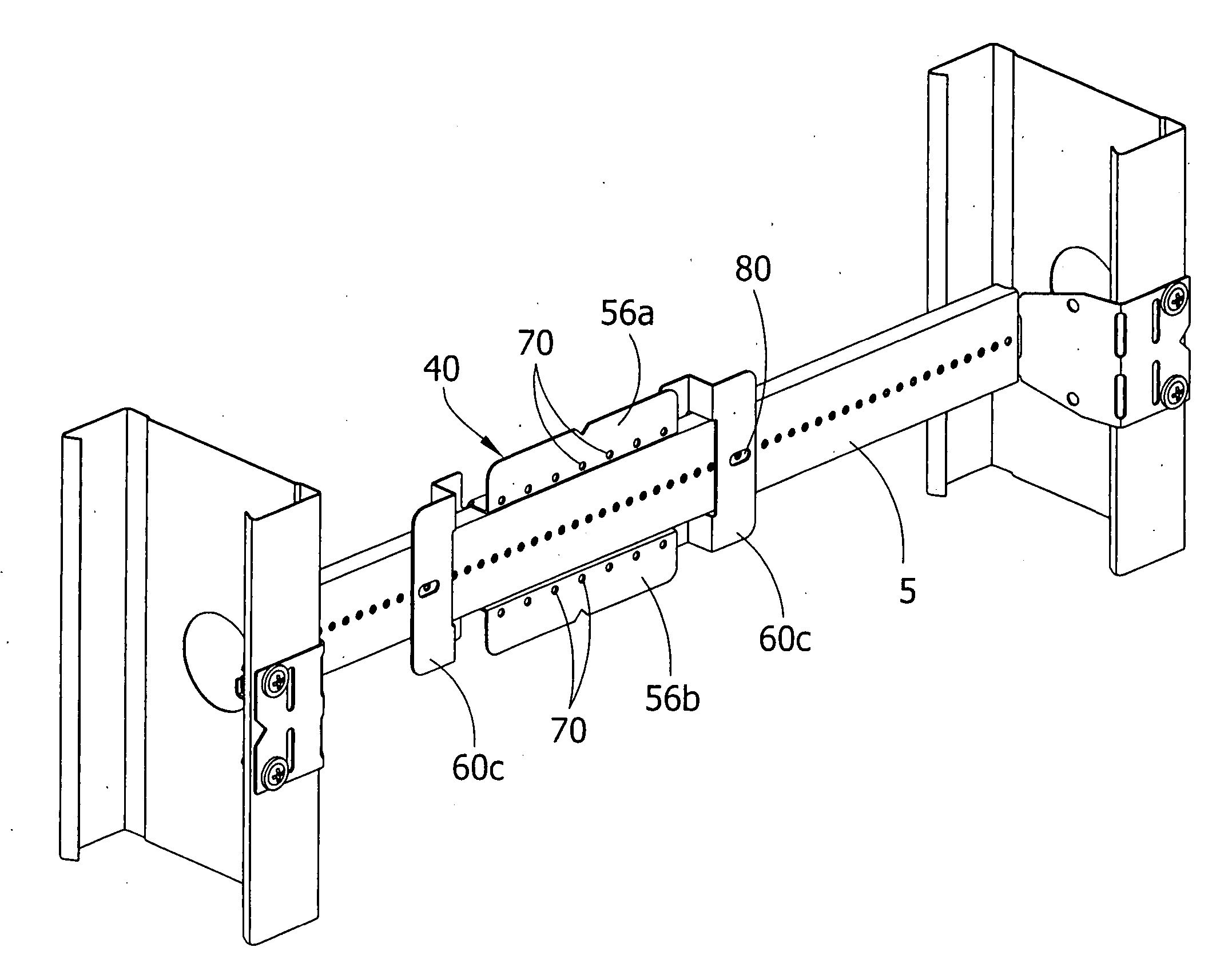
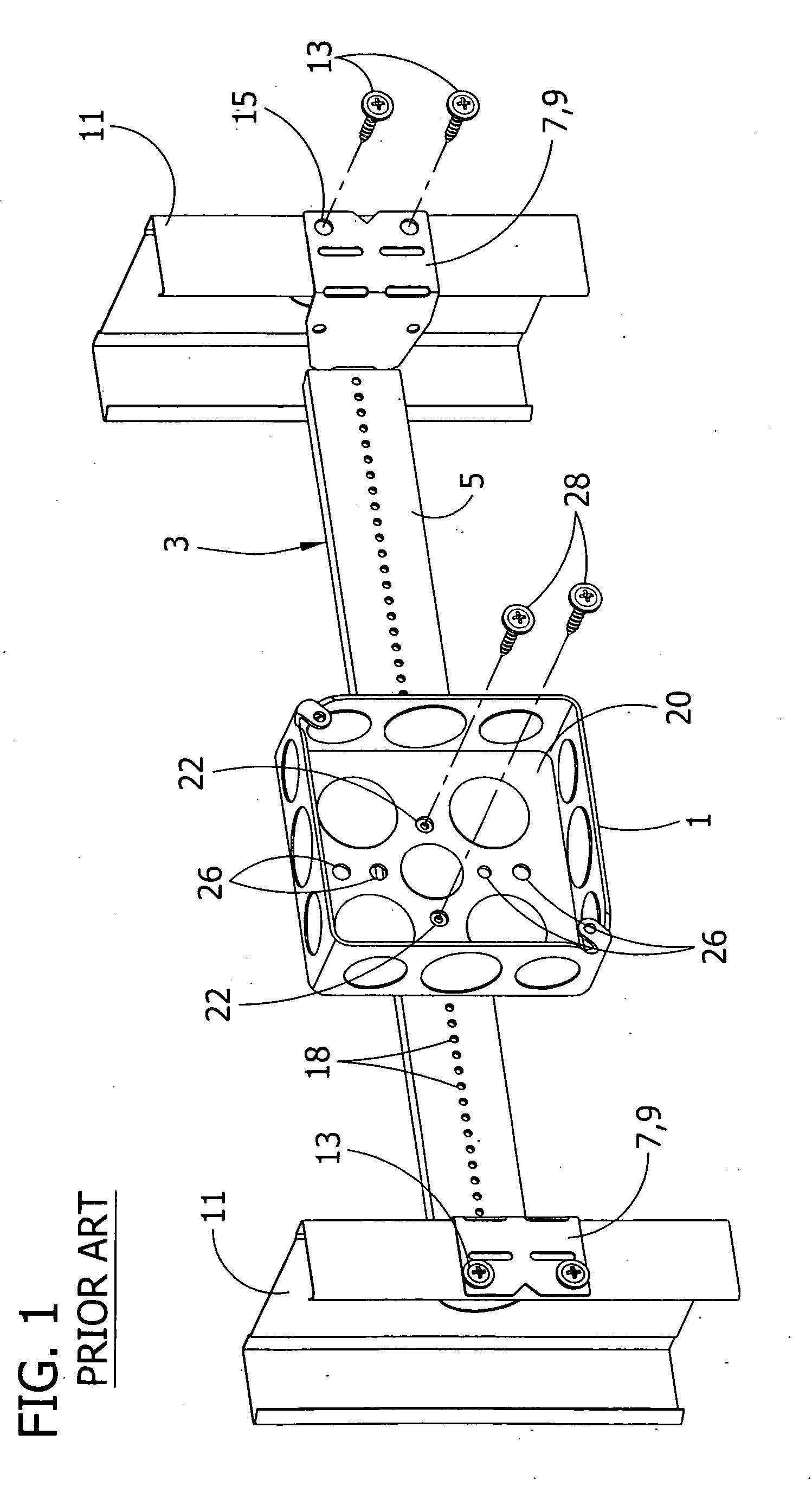
[0025] Referring now to the drawings, FIG. 1 illustrates an electrical box 1 secured to a horizontal mounting bar device, generally indicated at 3. The illustrated mounting bar device 3 is of the type generally referred to as an adjustable mounting bar or a telescoping bar. An exemplary adjustable mounting bar is described in detail in U.S. Pat. No. 5,209,444, which is herein incorporated by reference. The horizontal mounting bar device 3 comprises a generally elongate mounting section 5 and a pair of fastening sections 7 at opposite ends of the mounting section. The fastening sections 7, comprising a pair of fastening flaps 9, are secured to a pair of spaced apart wall studs 11 such that the mounting section 5 of the bar device 3 extends generally horizontally between the studs. Suitable fasteners 13 are inserted through openings 15 in the fastening flaps 9 to secure the flaps to the studs 11. The mounting section 5 of the bar device 3 has a series of aligned box fastening openings...


PUM


Abstract

This invention relates to a bracket for mounting an electrical box on a mounting bar device. The bracket has a central section having a channel-shaped recess. The bracket also has end sections at opposite ends of the central section. The end section have bar device openings that are generally aligned with the channel-shaped recess of the central section. The bar device openings and the channel-shaped recess are adapted to slidably receive the mounting bar device. The electrical box is secured to the central section of the bracket using a first fastener element. The bracket is secured to the mounting bar device using a second fastener element. The bracket may also be convertible for use in mounting an electrical box on a vertical mounting rod.

Description

BACKGROUND OF INVENTION [0001] This invention relates generally to a device for mounting an electrical box, and more particularly, to a bracket which is particularly suited for mounting a pre-wired electrical box. Electrical boxes (also referred to as “junction boxes”) are used to house and protect electrical devices such as electrical outlets, switches and associated wiring when the devices are installed in a building. Typically, an electrical device is installed either by securing the junction box containing the device directly to framing within the structure, or by securing the box to a mounting device that is fastened to such framing. One such box mounting device is described in U.S. Pat. No. 5,209,444. The device comprises a mounting bar having fastening flaps at opposite ends of the bar for securement to spaced apart wall studs. When the flaps are secured to the studs, the bar extends generally horizontally between the studs. The bar has a generally channel-shaped cross-sectio...

Claims


Application Information

Patent Timeline
Patent Type & Authority Applications(United States)
IPC IPC(8): E04G25/00
CPCH02G3/125Y10S248/906
Inventor RINDERER, ERIC R.
Owner EATON INTELLIGENT POWER LIMITED
Why Eureka
Try Eureka