Vehicular image display apparatus

Inactive Publication Date: 2006-11-02
DENSO CORP
View PDF10 Cites 42 Cited by
  • Summary
  • Abstract
  • Description
  • Claims
  • Application Information

AI Technical Summary

Benefits of technology

[0007] It is an object of the present invention to provide a vehicular image display apparatus allowing an image, which

Problems solved by technology

If an obstacle displayed in the monitor, it is difficult for a driver to intuitively notice a positional relati

Method used


Image

  • Vehicular image display apparatus
  • Vehicular image display apparatus
  • Vehicular image display apparatus

Examples


Embodiment Construction

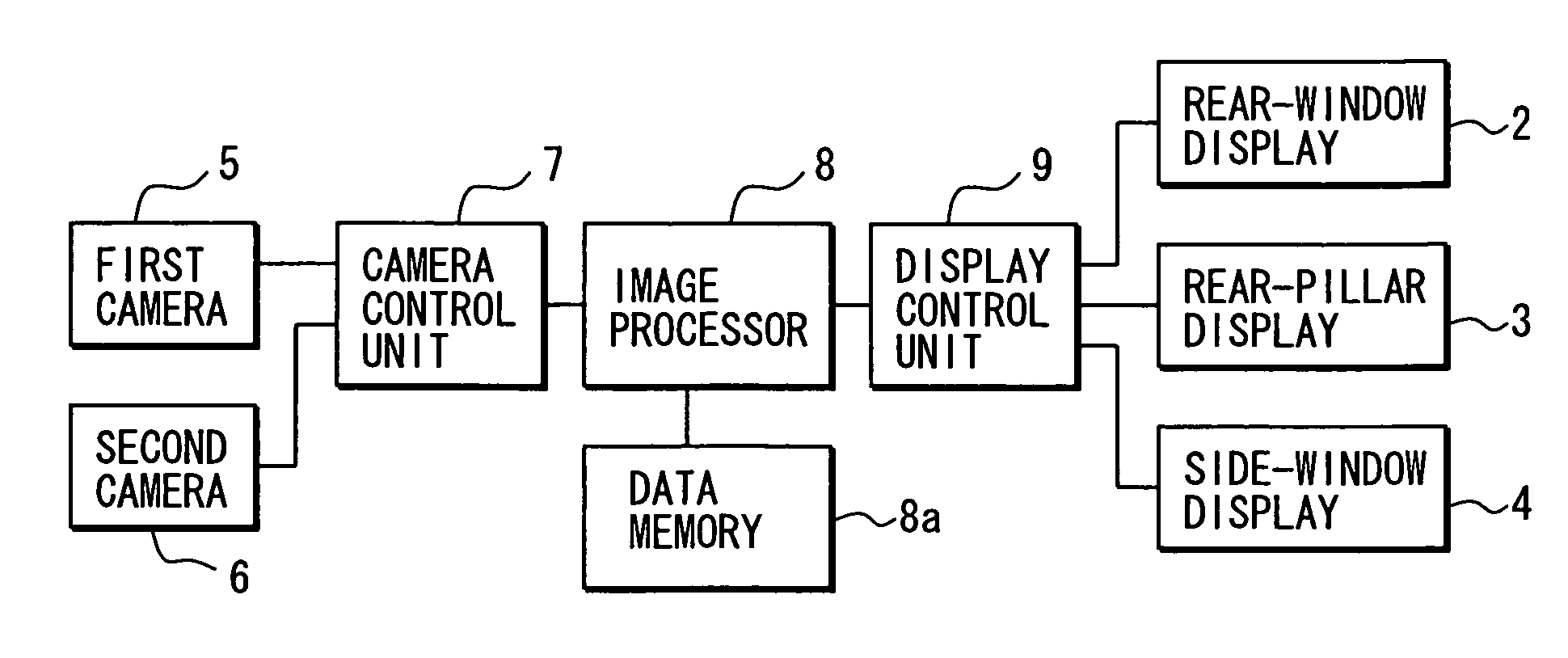
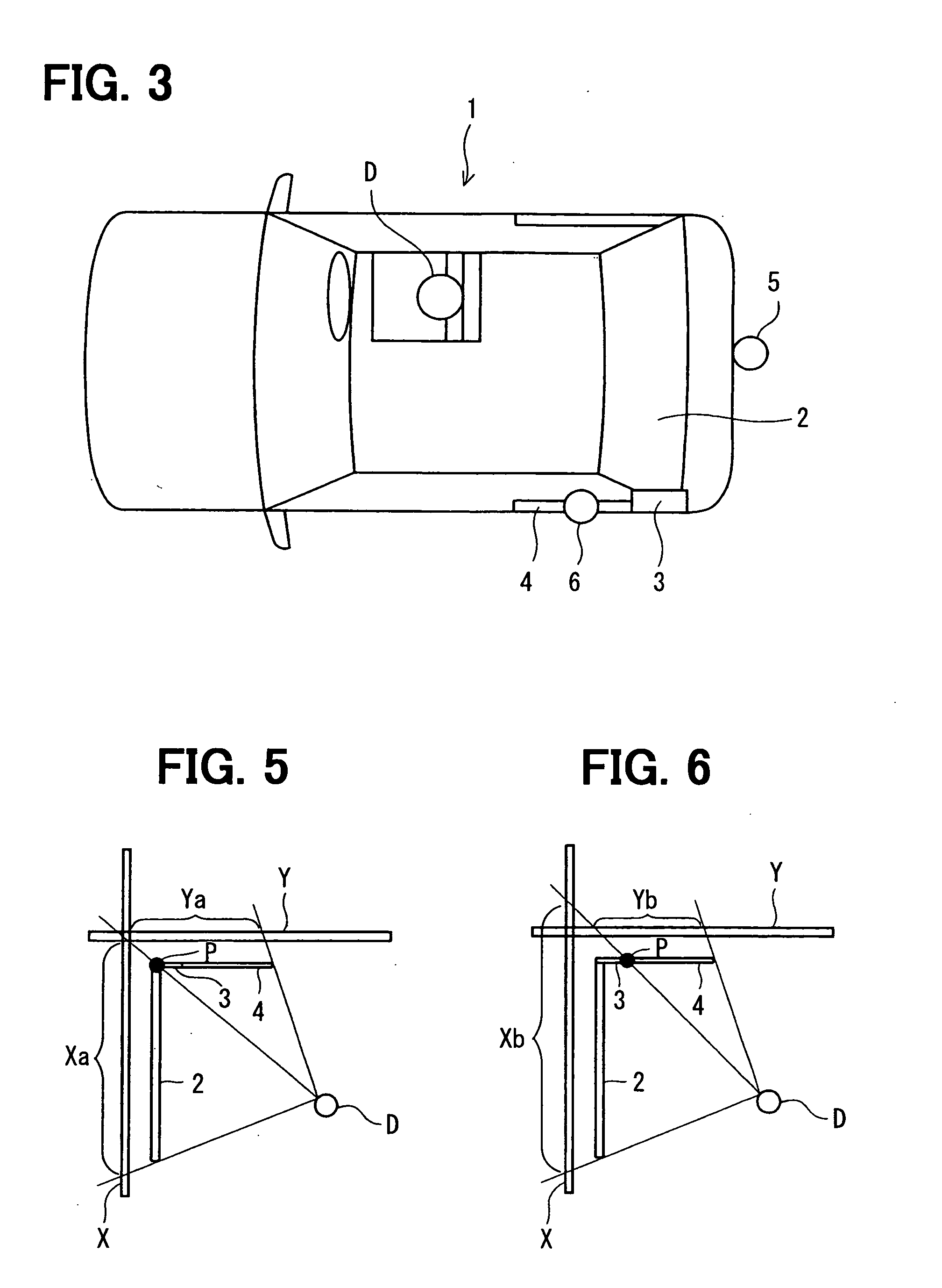
[0017] A vehicle 1 with right-hand drive is a hatchback-type vehicle, as shown in FIG. 3. A seat of a driver D of the vehicle 1 is adjacent to a right side (right side wall) (relative to an advancing direction of the vehicle) of the vehicle. A rear-window display 2 of, e.g., a transparent-type EL (Electroluminescence) panel as a first sub-display is placed in a rear window as a part of a rear (rear wall) of the vehicle 1. A rear-pillar display 3 of, e.g., an EL panel is placed inside of a left rear pillar as a part of a left side (left side wall) of the vehicle 1. A side-window display 4 of, e.g., a transparent-type EL panel is placed in a rear side window as a part of the left side of the vehicle 1. A pair of the rear-pillar display 3 and the side-window display 4 is referred to as a second sub-display.

[0018] A first camera 5 is placed at an outer rear portion of the vehicle 1. The first camera 5 has a circular fish-eye lens of a 180-degree ultrawide-angle to take an image from a ...


PUM


Abstract

A vehicle is provided with two circular fish-eye lens-type cameras and three displays of a rear-window display, rear-pillar display, and side-window display. The first camera takes an image from a first region rearward of the vehicle; the second camera takes an image from a second region left sideward of the vehicle. The first and second regions are partially overlapped. Ultrawide-angle image data of the taken images are converted to typical lens image data, a part of which is clipped to correspond to an integrated region. The integrated region including a part of the first and second regions is viewed by an artificial driver sightline, which is assumed to pass through entire frames of the three displays to reach the integrated region. The three displays then reproduce an image of the integrated region without overlap based on the clipped image data.

Description

CROSS REFERENCE TO RELATED APPLICATIONS [0001] This application is based on and incorporates herein by reference Japanese Patent Application No. 2005-132101 filed on Apr. 28, 2005. FIELD OF THE INVENTION [0002] The present invention relates to a vehicular image display apparatus for displaying an image which a camera takes from a region surrounding a vehicle. BACKGROUND OF THE INVENTION [0003] A driver of a vehicle has a blind zone typically rearward or sideward, which may be shaded by a rear trunk (in a sedan-type vehicle), a hatchback door (in a hatchback-type vehicle), or a rear pillar. For instance, a vehicle with right-hand drive typically has a relatively large blind zone left rearward of the vehicle. To deal with the problem, in Patent Documents 1, 2, a camera is provided to take an image from the blind zone; then, the taken image is displayed (or reproduced) in a monitor placed frontward or rearward of a driver's seat. [0004] In this case, a taken image from an actual given ...

Claims


Application Information

Patent Timeline
IPC IPC(8): H04N7/18H04N9/47
CPCB60R1/00B60R2300/105B60R2300/106B60R2300/303H04N5/2624B60R2300/802B60R2300/8053B60R2300/8066B60R2300/404
Inventor KATO, MIKIOYOSHIDA, ICHIRO
Owner DENSO CORP
Why Eureka
Try Eureka