Apparatus and method for controlling work tool vibration

a technology for working tools and vibration, applied in the direction of rotary clutches, fluid couplings, couplings, etc., can solve the problems of other functions, tedious and tiring, and the technique is only limited to certain work functions

Active Publication Date: 2006-11-09
CATERPILLAR INC
View PDF4 Cites 16 Cited by
  • Summary
  • Abstract
  • Description
  • Claims
  • Application Information

AI Technical Summary

Benefits of technology

[0009] In another aspect of the present invention, a work machine is provided. The work machine may include a work tool, first and second actuators, a vibration control device, a work tool control device, and a controller. The first actuator may be operably coupled to the work tool for changing the position of the work tool and may be operable in a vibratory mode and in a non-vibratory mode. The second actuator also may be operably coupled to the work tool for changing the position of the work tool and may be operable in a vibratory mode and in a non-vibratory mode. The vibration control device may be operable to generate a ...

Problems solved by technology

This method involves rapid motion by the operator that, over time, can become tedious and tiring.
This technique is also only limited to certain work functions, such as shaking material out of the tool.
Other functions, such as vibratory compaction of a surface, may not be efficien...

Method used


Image

  • Apparatus and method for controlling work tool vibration
  • Apparatus and method for controlling work tool vibration
  • Apparatus and method for controlling work tool vibration

Examples


Embodiment Construction

[0016] Reference will now be made in detail to embodiments or features of the invention, examples of which are illustrated in the accompanying drawings. Wherever possible, the same or corresponding reference numbers will be used throughout the drawings to refer to the same or corresponding parts.

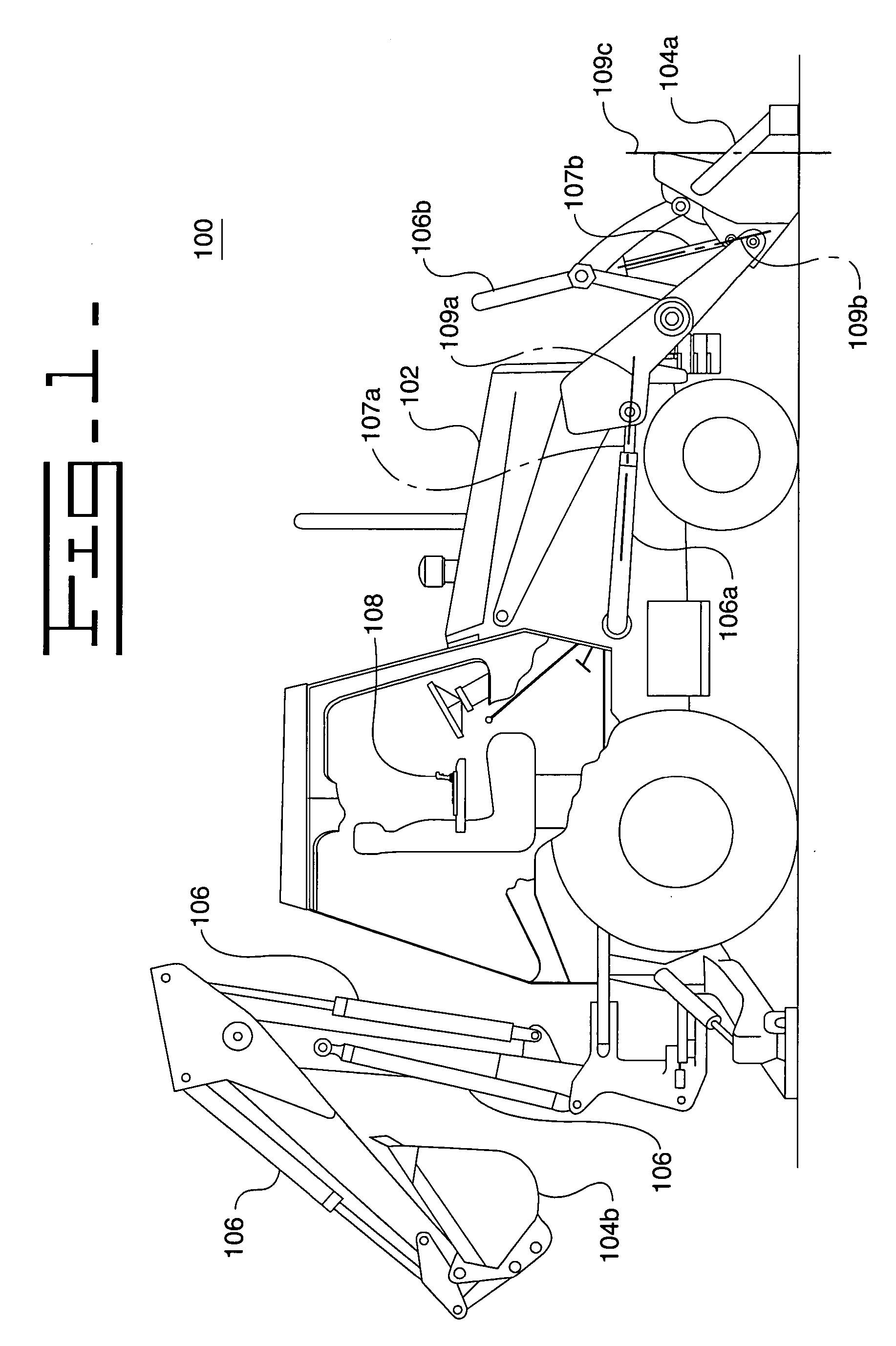
[0017] With reference to FIG. 1, an example of a work machine 102 suited for use with the present invention is shown. The work machine 102 is shown as an earthworking maching, and in particular, a backhoe loader. However, other types of earthworking machines may apply, such as excavators, wheel loaders, skid steer loaders, front shovels, and track loaders to name a few. Furthermore, the work machine 102 may be of a type other than an earthworking machine. For example, the work machine 102 may be a machine used for construction, material transfer, manufacturing, agriculture, and such, provided that the present invention may find application with the machine.

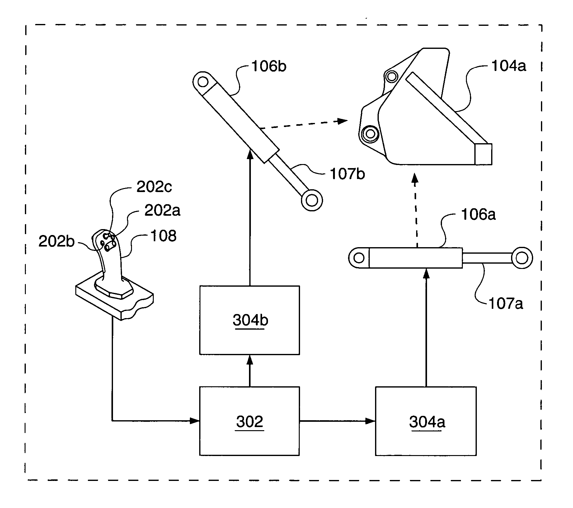
[0018] A work tool 104, mounted o...


PUM


Abstract

An apparatus and method for controlling a work tool on a work machine are provided. The work machine may have first and second actuators, each actuator being operable in a vibratory mode and a non-vibratory mode, and each actuator being coupled to the work tool for changing the position of the work tool. The method may include simultaneously (i) operating the first actuator in a vibratory mode, (ii) operating the second actuator in a vibratory mode, and (iii) receiving a command to change the position of the work tool. The method may further include operating the first actuator in a non-vibratory mode to change the position of the work tool while operating the second actuator in a vibratory mode to vibrate the work tool, in response to receiving the command.

Description

TECHNICAL FIELD [0001] This invention relates generally to a method and apparatus for controlling a work tool and, more particularly, to a method and apparatus for controlling vibratory motion of a work tool. BACKGROUND [0002] During operation of work machines, it is sometimes desirable to move a work tool in a vibratory manner to accomplish some purpose. For example, an operator of an earthworking machine having a work tool such as a bucket may desire to cause the bucket to move in a vibratory manner to (i) shake material out of the bucket that does not readily fall out, (ii) cause the bucket to penetrate hard material such as clay or rock, (iii) compact a surface, or (iv) perform some other function. [0003] In the past, the standard method for vibrating a work tool has been for an operator to rapidly move the work tool control, such as a joystick or lever, back and forth until the task was completed. This method involves rapid motion by the operator that, over time, can become ted...

Claims


Application Information

Patent Timeline
IPC IPC(8): F16D31/02
CPCE02F9/221
Inventor BUCKMIER, JASON M.COCKMAN, DANIEL A.GRAHAM, LUKE E.HOESSLER, GILLESMESSER, DAVID L.MOST, W. RYAN
Owner CATERPILLAR INC
Why Eureka
Try Eureka