Tamper-proof container

a container and tamper-proof technology, applied in the field of security systems, can solve the problems of damage to the liner sheet, optical path broken or altered, and impingement on the liner sheet, and achieve the effect of reducing or altering the light transmissibility of the optical path

Active Publication Date: 2006-11-09
3D FUSE TECH
View PDF51 Cites 13 Cited by
  • Summary
  • Abstract
  • Description
  • Claims
  • Application Information

AI Technical Summary

Benefits of technology

[0011] For example, a breach of the container or box can break the optical path by cutting the core of the optical fiber which is typically 10 to 100 microns in diameter. The destruction of the core, causes an instantaneous and complete loss of light transmission. Thus the optical fiber acts as a true binary switch, it is either on or off; light conducting or non-conducting. This “binary switch” is in effect passing a single binary bit of information around the single continuous light path i.e. light signal is present or it is not present. The system is in effect “an optical fuse”, and analag

Problems solved by technology

At least one liner sheet lines at least a portion of at least one interior surface of the shipping container or box, such that a physical breach of the portion of the interior surface also damages the liner sheet, or radiation from a radioactive source, such as a nuclear or radiological weapon, impinges on the liner sheet.
If the container or box interior surface is breached or

Method used


Image

  • Tamper-proof container
  • Tamper-proof container
  • Tamper-proof container

Examples


Embodiment Construction

[0043] The contents of the U.S. patent applications identified above are all hereby incorporated by reference herein.

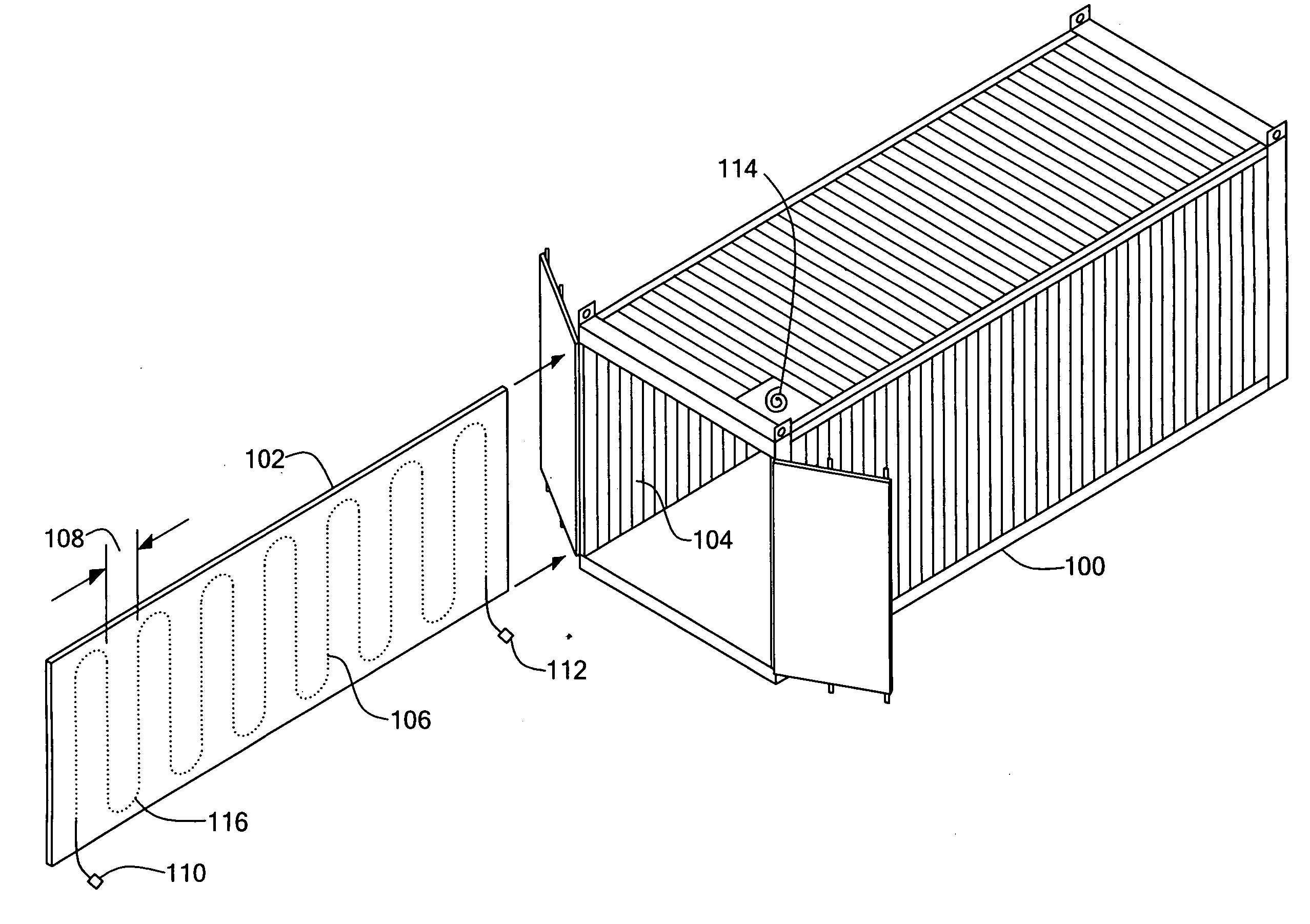
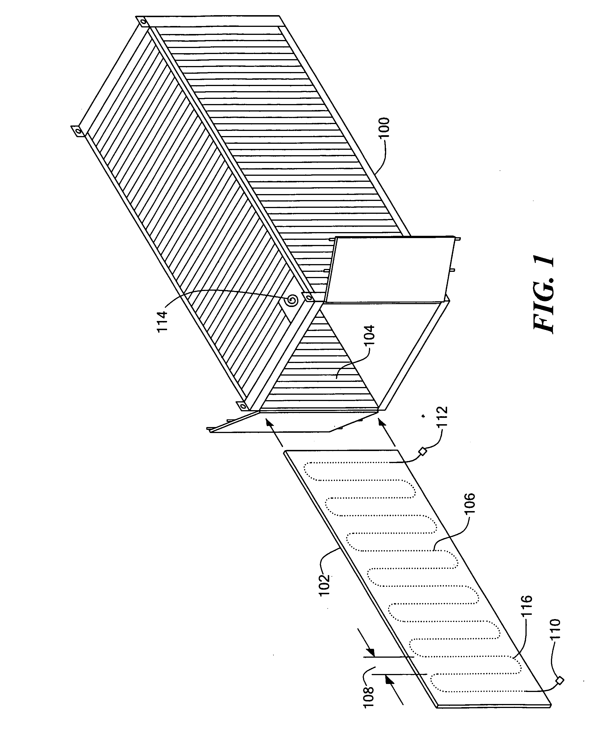
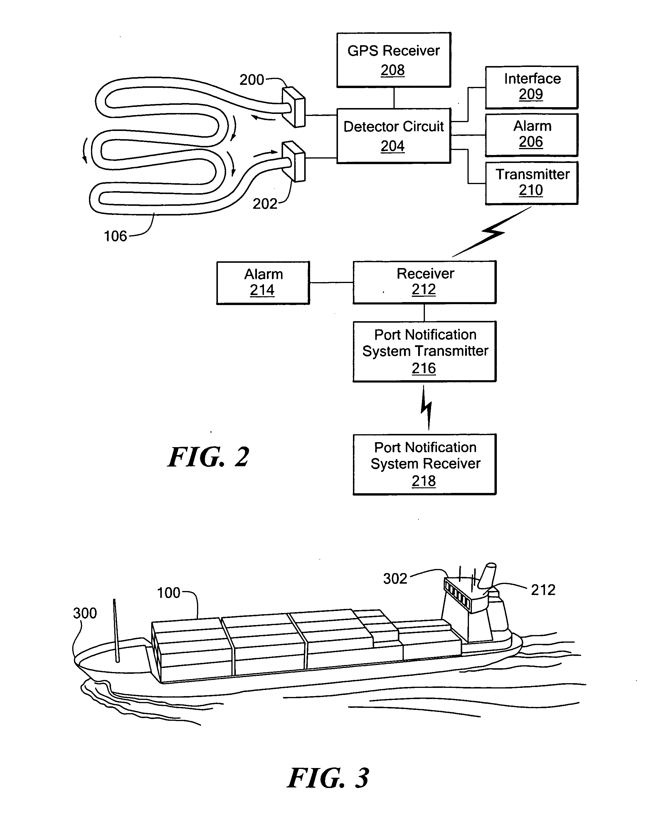
[0044] The present invention provides methods and apparatus to detect tampering with a six-sided or other type of container or box or other surface or a source of radiation within or near the container, box or surface, as well as methods of manufacturing such apparatus. A preferred embodiment detects a breach in a monitored surface of a container, box or fence or radiation from a source. A liner sheet lines at least a portion of an interior surface of the container, box or fence, such that a breach of the portion of the container interior surface or fence damages the liner sheet or radiation from the source impinges on at least a portion of the liner sheet. The liner sheet defines an optical path extending across at least a portion of the sheet. For example, an optical fiber can be woven into, or sandwiched between layers of, the liner sheet. The optical path is moni...


PUM


Abstract

A system and method for detecting radiation from a source in a container is disclosed. A continuous optical fiber path is disposed in a medium which is part of or associated with a container and which encloses the volumetric space of the container. The optical fiber path provides a volumetric mass of optical fiber which is reactive to radiation from a radiation source in the container to cause an irreversible change in the light carrying capacity or other characteristic of the optical fiber. A light source is coupled to one end of the optical fiber path for introducing light having a predetermined characteristic. A light detector is coupled to the other end of the optical path for receiving light from the optical path. A circuit is coupled to the light detector and is operative to detect a change in the predetermined characteristic of the light and to provide an indication thereof.

Description

CROSS-REFERENCE TO RELATED APPLICATIONS [0001] This application is a continuation-in-part of U.S. patent application Ser. No. 10 / 981,836 filed Nov. 5, 2004, titled “Tamper Proof Container”. This application claims the benefit of U.S. Provisional Application No. 60 / 706,501, titled “Tamper Proof Container,” filed Aug. 8, 2005 and U.S. Provisional Application No. 60 / 687,409, titled “Tamper Proof Container,” filed Jun. 3, 2005. [0002] This application is related to U.S. patent application Ser. No. 11 / 027,059, titled “Tamper Proof Container,” filed Dec. 30, 2004, now U.S. Pat. No. 6,995,353, U.S. patent application Ser. No. 11 / 349,049, titled “Tamper Proof Container,” filed Feb. 7, 2006, and U.S. patent application Ser. No. 10 / 837,883, titled “Tamper Proof Container,” filed May 3, 2004.STATEMENT REGARDING FEDERALLY SPONSORED RESEARCH OR DEVELOPMENT [0003] (Not Applicable) BACKGROUND OF THE INVENTION [0004] 1. Field of the Invention [0005] The present invention relates to security systems...

Claims


Application Information

Patent Timeline
IPC IPC(8): G01J1/04G01J5/08
CPCG01J1/04G01J1/0425G01J1/42G08B13/186G01T1/167G01V5/0075G08B13/10G01N21/21
Inventor BEINHOCKER, GILBERT D.
Owner 3D FUSE TECH
Why Eureka
Try Eureka