Lower extremity exoskeleton

a lower extremity and exoskeleton technology, applied in the field of lower extremity exoskeletons, can solve the problems of people being frustrated in attempting to carry excessively heavy or bulky objects while walking, and people cannot even carry their own weight, so as to achieve the effect of quickly tiredness or injury

Active Publication Date: 2006-11-23
RGT UNIV OF CALIFORNIA
View PDF32 Cites 186 Cited by
  • Summary
  • Abstract
  • Description
  • Claims
  • Application Information

AI Technical Summary

Benefits of technology

[0007] In one exemplary embodiment, a lower extremity exoskeleton is configurable to be coupled to a person. The lower extremity exoskeleton comprises two leg supports configurable to be coupled to the person's lower limbs and configured to rest on the ground during their stance phases. Each leg support comprises a thigh link, a shank link, and two knee joints. Each knee joint is configured to allow flexion and extension between the respective shank link and the respective thigh link. The lower extremity exoskeleton also comprises an exoskeleton trunk configurable to be coupled to the person's upper body. The exoskeleton trunk is rotatably connectable to the thigh links of the leg supports allowing for the flexion and extension between the leg supports and the exoskeleton trunk. In this exemplary embodiment, the energy required for flexion and extension movement between the shank link and the respective thigh link of a leg support over a cyclic knee motion is provided by the person.

Problems solved by technology

In a wide variety of situations, people are often frustrated in attempting to carry excessively heavy or bulky objects while walking.
Some people cannot even carry their own weights without becoming tired quickly or injured.

Method used


Image

  • Lower extremity exoskeleton
  • Lower extremity exoskeleton
  • Lower extremity exoskeleton

Examples


Embodiment Construction

[0045] The following description sets forth numerous specific configurations, parameters, and the like. It should be recognized, however, that such description is not intended as a limitation on the scope of the present invention, but is instead provided as a description of exemplary embodiments.

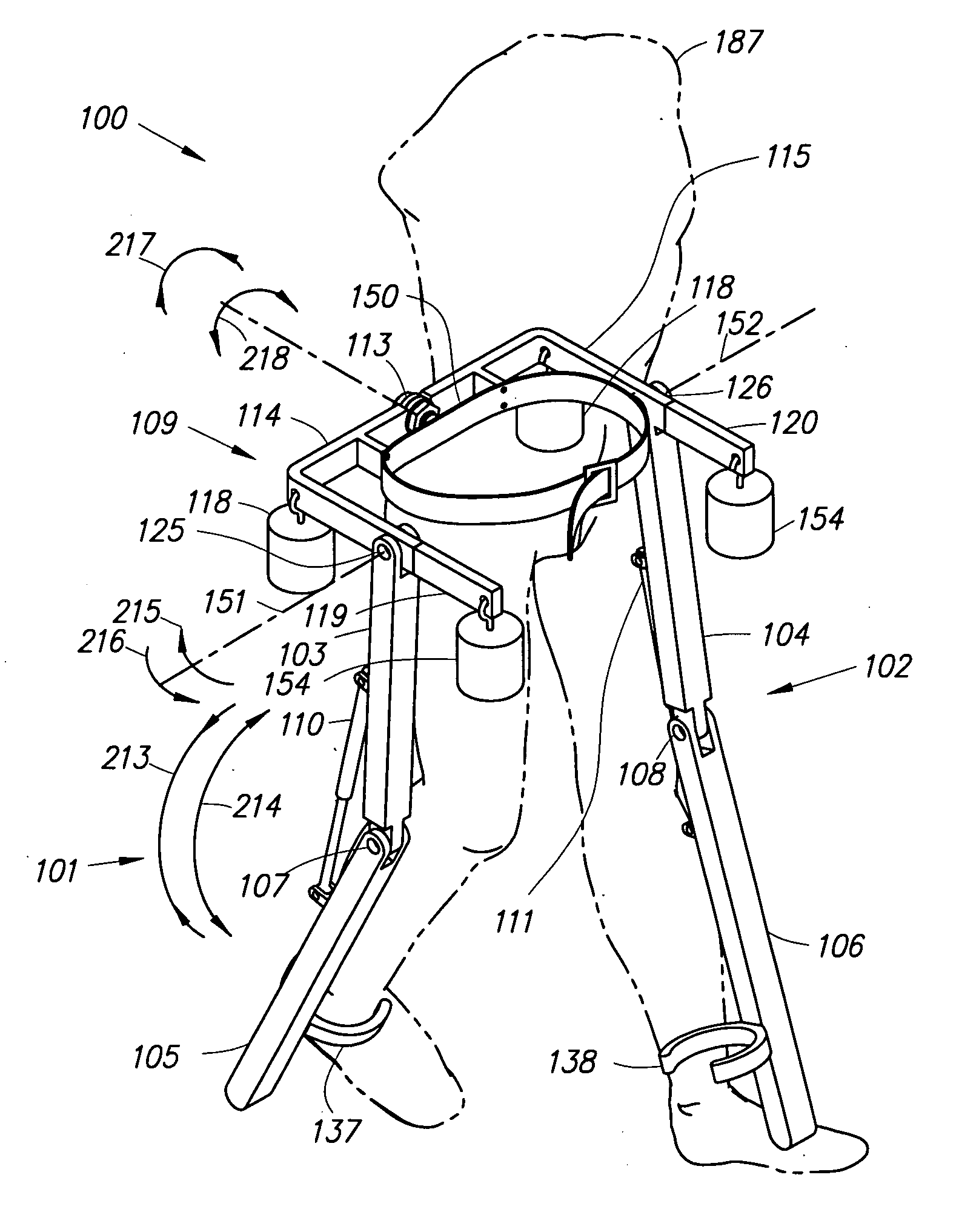
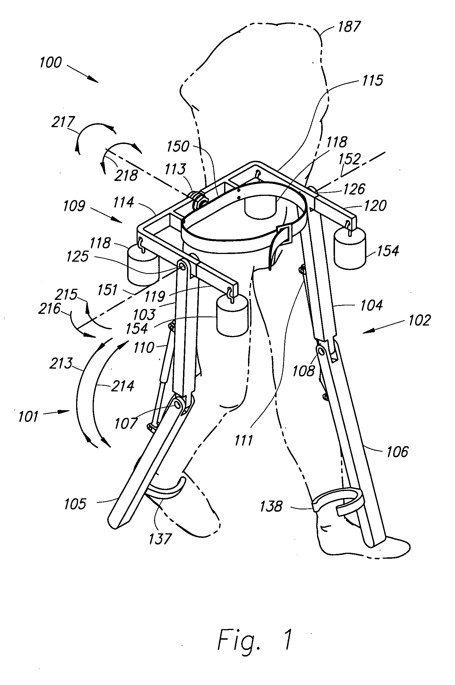
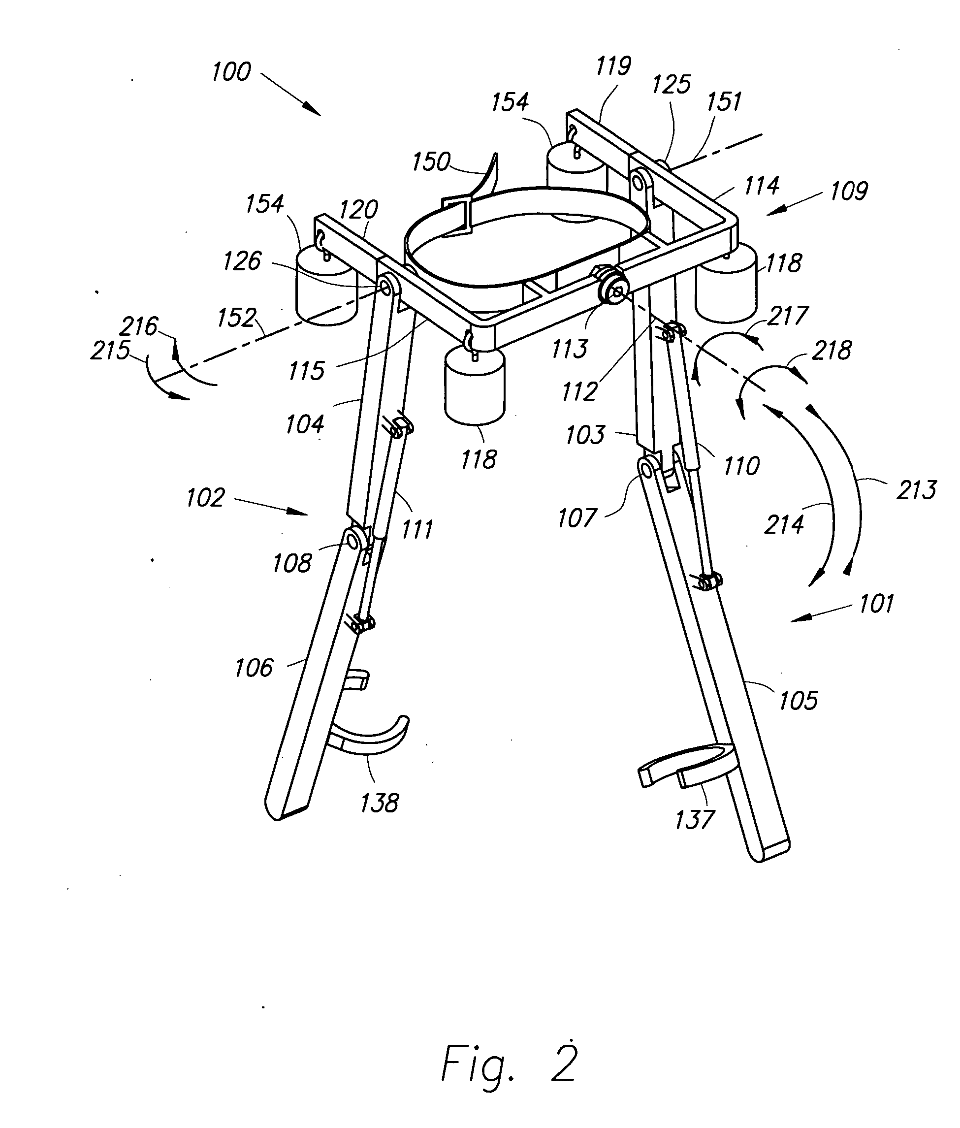
[0046] In accordance with an embodiment of the present invention, FIGS. 1 and 2 are front view and rear view perspective drawings illustrating a lower extremity exoskeleton 100. Lower extremity exoskeleton 100 is configurable to be coupled to a person 187. Lower extremity exoskeleton 100 comprises two leg supports 101 and 102 which are configurable to be coupled to the person's lower limbs and configured to rest on the ground during the stance phase of each leg support. The leg supports comprise thigh links 103 and 104 and shank links 105 and 106. Two knee joints 107 and 108 are configured to allow flexion and extension (shown by arrows 213 and 214 respectively) between the shank link and t...


PUM


Abstract

A lower extremity exoskeleton, configurable to be coupled to a person, comprises two leg supports configurable to be coupled to the person's lower limbs and configured to rest on the ground during their stance phases. Each leg support comprises a thigh link, a shank link, and two knee joints. Each knee joint is configured to allow flexion and extension between the respective shank link and the respective thigh link. The lower extremity exoskeleton also comprises an exoskeleton trunk configurable to be coupled to the person's upper body. The exoskeleton trunk is rotatably connectable to the thigh links of the leg supports allowing for the flexion and extension between the leg supports and the exoskeleton trunk. In this exemplary embodiment, the energy required for flexion and extension movement between the shank link and the respective thigh link of a leg support over a cyclic knee motion is provided by the person.

Description

CROSS-REFERENCE TO RELATED APPLICATIONS [0001] This application claims the benefit of U.S. Provisional Application No. 60 / 645,417, titled LOWER EXTREMITY EXOSKELETON, filed Jan. 18, 2005, the entire content of which is incorporated herein by reference.STATEMENT REGARDING FEDERALLY SPONSORED RESEARCH OR DEVELOPMENT [0002] This invention was made with government support under Contract No. DAAD19-01-1-0509 awarded by Defense Advanced Research Projects Agency (DARPA). The government has certain rights in the invention.BACKGROUND [0003] 1. Field [0004] The present application relates generally to the field of lower extremity exoskeletons and more specifically to the field of low power lower extremity exoskeletons. [0005] 2. Related Art [0006] In a wide variety of situations, people are often frustrated in attempting to carry excessively heavy or bulky objects while walking. Some people cannot even carry their own weights without becoming tired quickly or injured. Opportunities exist, the...

Claims


Application Information

Patent Timeline
Patent Type & Authority Applications(United States)
IPC IPC(8): A61G15/00
CPCA61B5/1038A61B5/4528B25J9/0006A61B2562/0219A61F5/0102A61B5/6829
Inventor KAZEROONI, HOMAYOONHARDING, NATHAN H.ANGOLD, RUSSDON
Owner RGT UNIV OF CALIFORNIA
Why Eureka
Try Eureka