
Bush type hydraulic rubber mount and method of making same

Inactive Publication Date: 2006-11-23
DTR
View PDF4 Cites 34 Cited by
  • Summary
  • Abstract
  • Description
  • Claims
  • Application Information

AI Technical Summary

Benefits of technology

[0012] Therefore, the present invention has been made in view of the above problems. It is an object of the invention to provide a bush type hydraulic rubber mount, which can obtain a hydraulic damping effect in axial direction and be mounted in the vertical direction of a vehicle.

Problems solved by technology

With the mount 100 of FIG. 1, it is difficult to obtain a high rigidity in axial direction.
When it needs to be mounted in the vertical direction of a vehicle, it has a disadvantage of not being able to obtain an axial hydraulic damping effect.
Furthermore, with the bush type hydraulic rubber mount 100, it is not possible to control the axial and radial rigidities independently.

Method used


Image

  • Bush type hydraulic rubber mount and method of making same
  • Bush type hydraulic rubber mount and method of making same
  • Bush type hydraulic rubber mount and method of making same

Examples


Embodiment Construction

[0031] Hereafter, the features of the invention will be explained in greater detail.

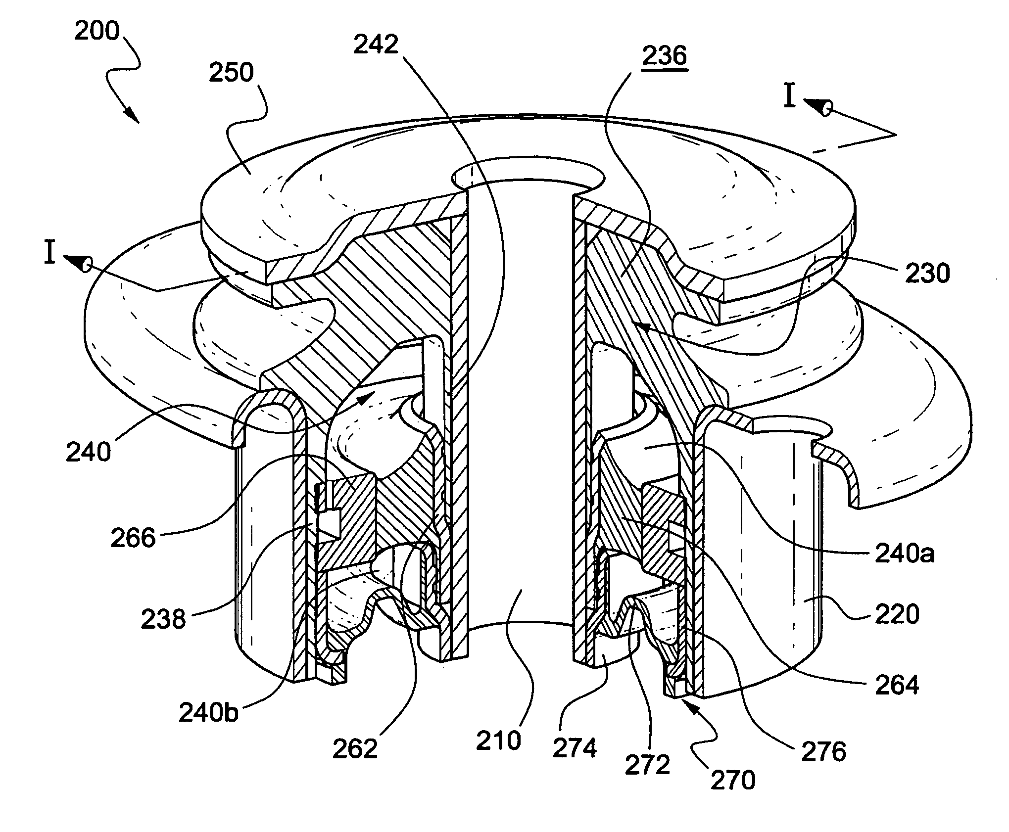
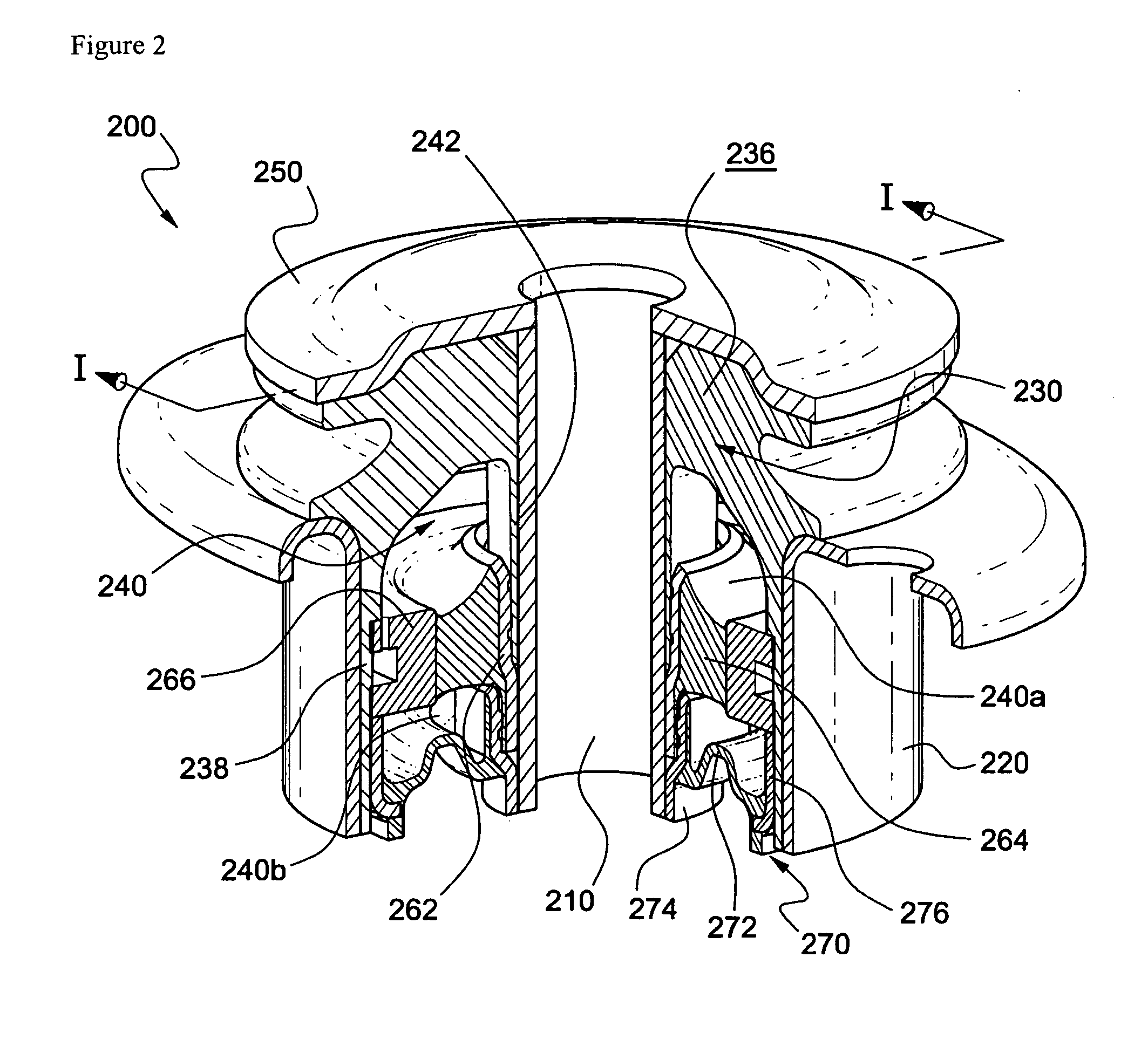
[0032]FIG. 2 is a partially exploded perspective view of a bush type hydraulic rubber mount according to the invention where the rubber mount of the invention is generally denoted by a reference numeral 200. FIG. 2 is a sectional view taken along the line I-I in FIG. 2.

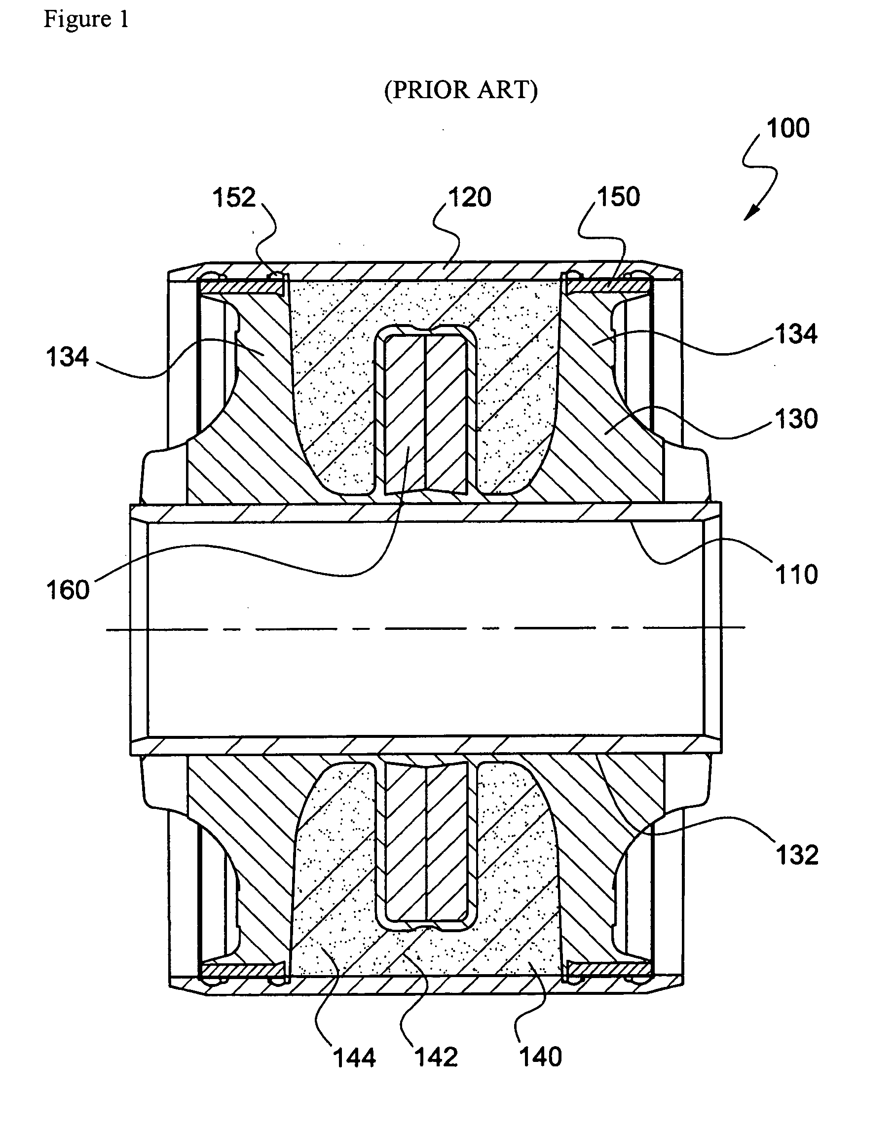
[0033] As illustrated in FIGS. 1 and 2, the bush type hydraulic rubber mount 200 of the invention includes an inner sleeve 210 and an outer sleeve 220 spaced apart from and surrounding the outer face of the inner sleeve 210. The inner sleeve 210 has a hollow cylindrical form. Similarly the outer sleeve 220 has a hollow cylindrical form and the upper end thereof is bent outwards so as to support a protrusion placed near the upper end of a first insulation rubber 230, which will be explained hereinafter.

[0034] The first insulation rubber 230 is mounted between the inner sleeve 210 and the outer sleeve 220. The first insulation rubber ...


PUM


Abstract

Disclosed are a vehicle mount to be installed between the body and the frame of a vehicle or the engine and the frame, and a method of manufacturing the mount. The vehicle mount includes an inner sleeve and an outer sleeve surrounding the outer face of the inner sleeve with a space in-between. A first insulation rubber is installed between the inner sleeve and the outer sleeve and forming an internal space in-between. The first insulation rubber has an inner sleeve insertion hole into which the inner sleeve is inserted. The first insulation rubber is contracted or expanded to attenuate external vibration and change a shape of the internal space according to an applied load. A space divider is installed in radial direction inside the internal space to divide the internal space into an upper first internal space and a lower second internal space. The space divider is provided at least one side thereof with an orifice connecting the first and second internal spaces to each other. A fluid is filled in the internal pace. The fluid flows between the first and second internal spaces depending on a difference in pressures exerted on the first and second internal spaces to attenuate external vibration. The vehicle mount provides an axial hydraulic damping effect and its axial and radial rigidities can be adjusted.

Description

BACKGROUND OF THE INVENTION [0001] 1. Field of the Invention [0002] The present invention relates to a mount and a method of manufacturing the same. In particular, the invention relates to a mount for vehicles and a method of manufacturing the same, which is installed between two structures, such as between a vehicle body and a frame or an engine and a frame, thereby buffering and absorbing impact and vibration transmitted between the two structures. [0003] 2. Background of the Related Art [0004] In general, a frame is an important portion supporting the load transmitted from the body and the reaction force from the front and rear shafts. A mount is disposed between the frame and the body and between the frame and the engine and the like, in order that impact or vibration transferred to the frame from the road surface is prevented from being transmitted to the body and the like, and problems caused from the direction connection between the two structures can be avoided. [0005]FIG. 1...

Claims


Application Information

Patent Timeline
IPC IPC(8): F16F13/00
CPCF16F13/16B60K5/12B62D24/02B62D27/04F16F7/12
Inventor KIM, TAE SUP
Owner DTR
Features
  • Generate Ideas
  • Intellectual Property
  • Life Sciences
  • Materials
  • Tech Scout
  • Unparalleled Data Quality
  • Higher Quality Content
  • 60% Fewer Hallucinations
Learn More