Synchronizing of a digital signal using a pcr program clock reference

a program clock and digital signal technology, applied in the field of sync, can solve problems such as time-generated delay and difficulty in synchronizing the clocks in the special memory card and the host device with each other

Inactive Publication Date: 2006-11-23
SOVEREIGN PEAK VENTURES LLC
View PDF15 Cites 13 Cited by
  • Summary
  • Abstract
  • Description
  • Claims
  • Application Information

AI Technical Summary

Benefits of technology

[0012] In view of the above problems residing in the prior art, an object of the present invention is to provide a digital signal receiving system constructed such that a digital signal receiving device configured as a special memory card, and a host device are interconnected with each other so as to securely recover synchronization of clocks in the special memory card and the host device, even in a poor radio wave receiving condition, as well as to provide the digital signal receiving device, the host device, and a semiconductor integrated circuit constituting the host device.

Problems solved by technology

In addition to the above, there is a greater problem to overcome: in what way clocks in the special memory card and the host device are synchronized with each other.
Consequently, in the case where the user switches over the channel, for example, there is generated delay in time because the clock information sent from the special memory card is received by the host device with a time lag corresponding to the data transfer time.
In addition to the above drawback, since the data transfer time is not constant, it is difficult to synchronize the clocks in the special memory card and the host device with each other.

Method used


Image

  • Synchronizing of a digital signal using a pcr program clock reference
  • Synchronizing of a digital signal using a pcr program clock reference
  • Synchronizing of a digital signal using a pcr program clock reference

Examples


first embodiment

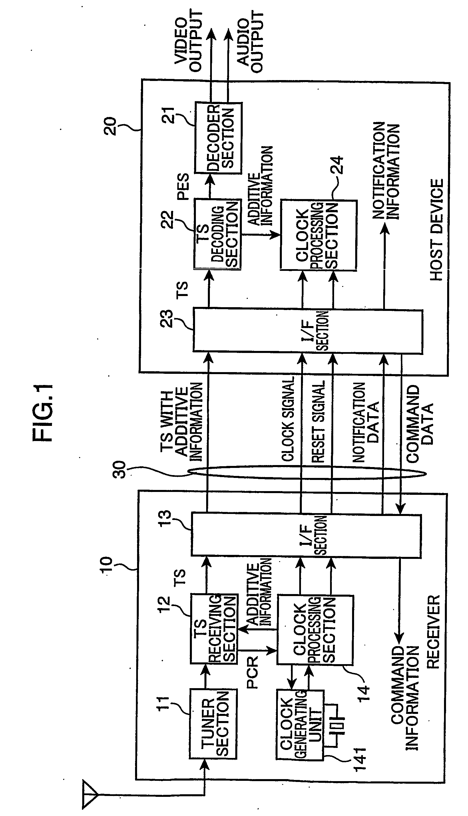
[0039]FIG. 1 is a block diagram showing an entire configuration of the digital broadcasting receiving system in accordance with the first embodiment of the present invention. First, the entire configuration of the digital broadcasting receiving system as the first embodiment is described referring to FIG. 1.

[0040] The digital broadcasting receiving system as the first embodiment includes a digital broadcasting receiving device 10 (hereinafter, also called as “receiver 10”), a host device 20, and a digital interface 30 (hereinafter, also called as “digital I / F 30”). The receiver 10 is adapted to receive digital broadcasting, and decode a transport stream signal (hereinafter, also called as “TS” or “transport stream”) based on the received signal. The host device 20 is adapted to receive the decoded transport stream from the receiver 10, and decode signals such as video and audio signals based on the received transport stream. The digital interface 30 is adapted to transmit / receive t...

second embodiment

[0135] In the first embodiment, described is the case where the difference data, e.g., “(PCR−STC)” is transferred from the receiver 10 to the host device 20, as additive information, so that the counter values in the counters of the receiver and the host device are coincident with each other.

[0136] In this embodiment, described is an arrangement in which counter values in counters of a receiver and a host device are made coincident with each other, even if difference data is not properly transmitted to the host device due to a problem related to a transmission line for transmitting a transport stream signal including the difference data.

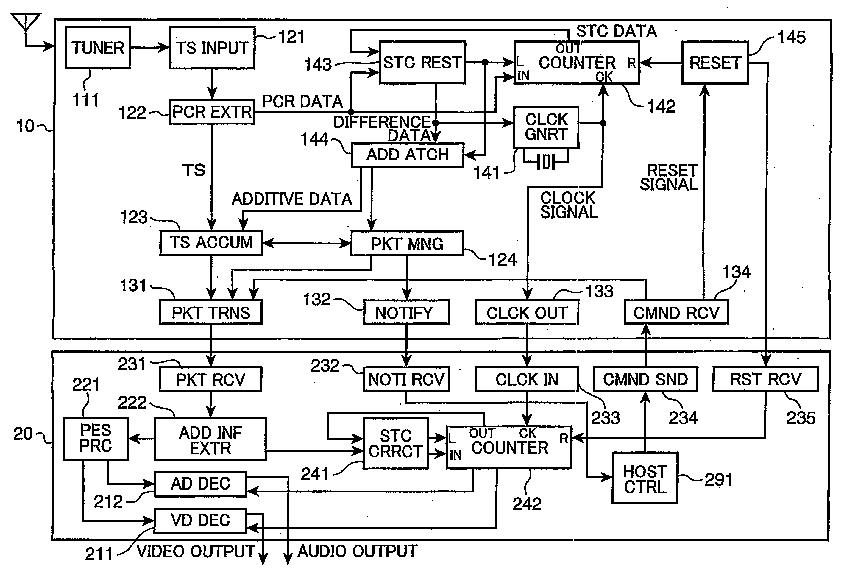
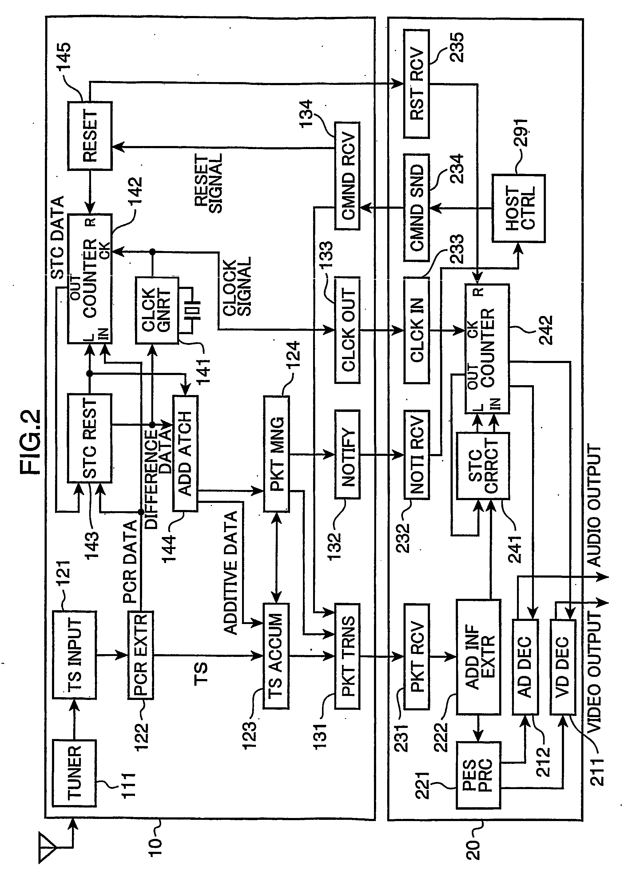
[0137]FIG. 8 is a block diagram showing a configuration of a digital broadcasting receiving device and a host device in a digital broadcasting receiving system in accordance with the second embodiment of the present invention. Functioning parts in FIG. 8 identified by the same reference numerals as in FIG. 2 have like functions as those in FIG. 2, ...

third embodiment

[0193] In the foregoing embodiments, the receiver 10 and the host device 20 are configured such that the respective elements or blocks (functioning parts) each having a certain function in the receiver 10 and the host device 20 may be constituted of individual semiconductor integrated circuits. Further alternatively, some of the elements may constitute a single semiconductor integrated circuit. The semiconductor integrated circuit may be, for instance, a large scale integration (LSI).

[0194] Some of the elements constituting the host device 20 in the first or second embodiment may constitute a functioning block. For instance, the host device 20 may be classified into the following four functioning blocks. The first functioning block is a counter correction block, which is constituted of the additive information extracting unit 222, the STC correcting unit 241, and the H_STC counter 242. The second functioning block is a control block, which is constituted of the host controlling uni...


PUM


Abstract

A digital signal receiving system is provided for establishing high-speed clock resynchronization even if abnormality such as a poor radio wave receiving condition takes place. The system is constructed such that recipient STC data and PCR data are acquired in response to detection of a variation in frequency of a clock signal, and these data are stored as variation information data. The receiver 10 sets the PCR data in the R_STC counter 142, and sends the variation information data to the host device 20. The host device 20, in turn, sets a computation result obtained based on host STC data and the variation information data in the H_STC counter 242.

Description

TECHNICAL FIELD [0001] The present invention relates to a digital signal receiving system, a digital signal receiving device, a host device, and a semiconductor integrated circuit suitable for receiving digital signals in movable objects. BACKGROUND ART [0002] In recent years, thanks to the development of digital technology of digitizing various information signals such as video and audio signals, a digital broadcasting system has been put into practical use, as well as the analog TV broadcasting. In such a digital broadcasting system, the MPEG2 system has been employed. In the MPEG2 system, contents data such as digitized video and audio data are packetized into transport stream packets (also called as “TS packets”). The TS packets are multiplexed, and transmitted as transport streams for digital broadcasting. There have been developed TV sets that enable to receive the digital TV broadcasting, as well as the analog TV broadcasting, and receivers dedicatedly used for the digital TV...

Claims


Application Information

Patent Timeline
Patent Type & Authority Applications(United States)
IPC IPC(8): H04N5/44G06K7/00H04B1/38H04L7/00H04N5/00H04N7/52H04N7/62H04N21/2368H04N21/43H04N21/434H04N21/442
CPCH04L7/0008H04N21/2368H04N21/44209H04N21/4341H04N21/4305H04B1/38H04N21/242
Inventor TAKEDA, HIDEYUKINADAMOTO, YUJI
Owner SOVEREIGN PEAK VENTURES LLC
Why Eureka
Try Eureka