Locking bone plate

a bone plate and locking technology, applied in the field of bone plates, can solve the problems of reducing surgical flexibility, limiting the choice of placement during surgery, and adding complexity to the procedure, and achieve the effect of greater flexibity of choi

Active Publication Date: 2006-11-23
GREATBATCH MEDICAL SA
View PDF91 Cites 115 Cited by
  • Summary
  • Abstract
  • Description
  • Claims
  • Application Information

AI Technical Summary

Benefits of technology

[0019] An object of the invention is to provide an orthopaedic surgeon greater flexibity of choice in that a threade

Problems solved by technology

Although an improvement over the inserts noted above, the locking positions are pre-defined, and only available in limited locations, which also reduce surgical flexibility.
This is not desirable because this requires more operating room tine and adds complexity to the procedure.
Further, the inserts must be added in the specific location before the plate is fixed to the bone and cannot be subsequently inserted.
This limits the choice of placement during surgery if the need arises.
Friction locks are not reliable and come lose more easily than threaded locked holes.
The result of such a design is inferior to that of the threaded plate and screw designs discussed below.
However, when such a bone plate is fixed to a bone, these

Method used


Image

  • Locking bone plate
  • Locking bone plate
  • Locking bone plate

Examples


Embodiment Construction

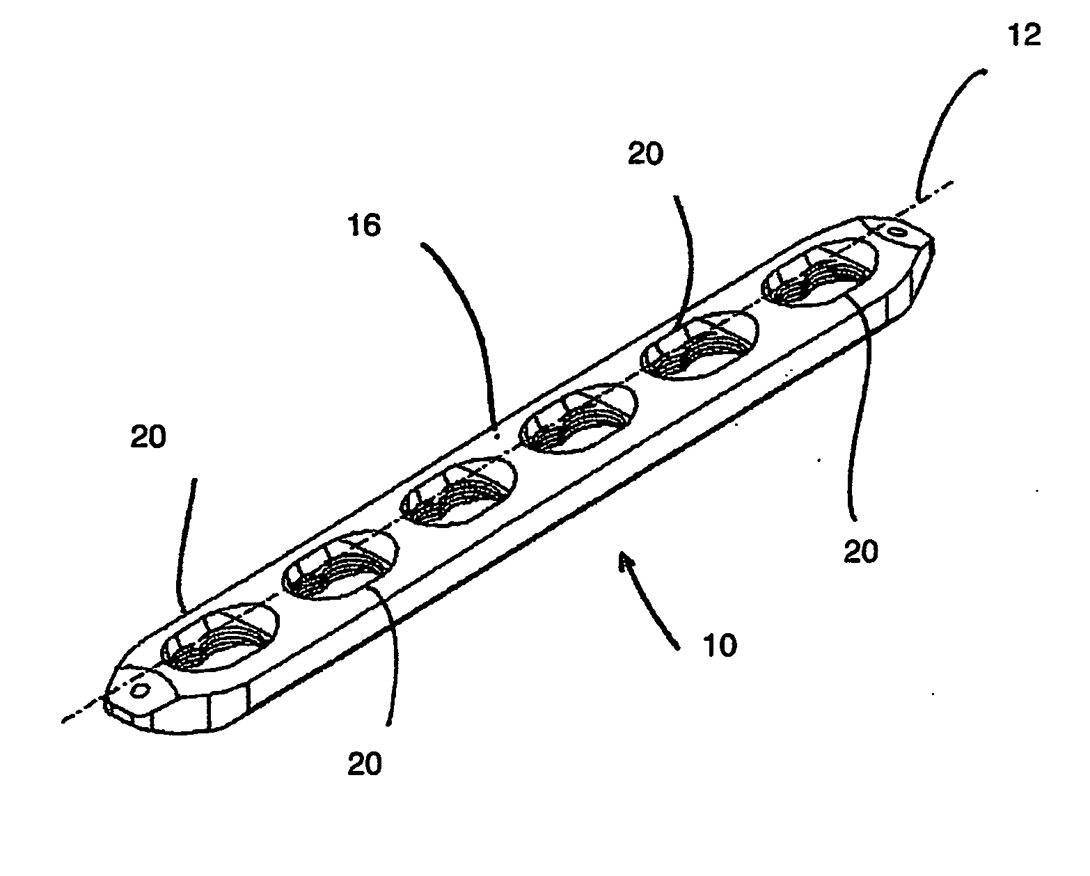
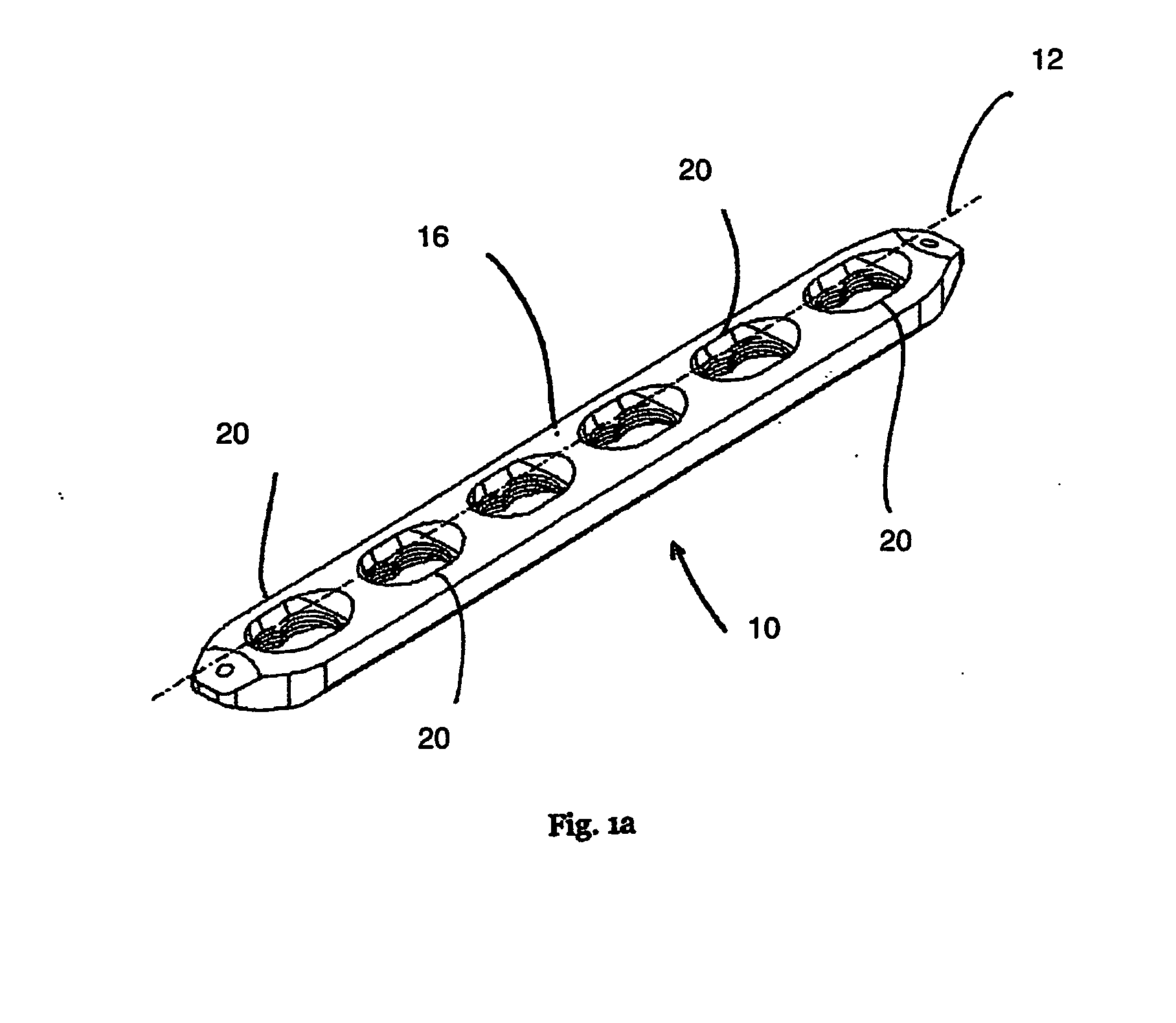
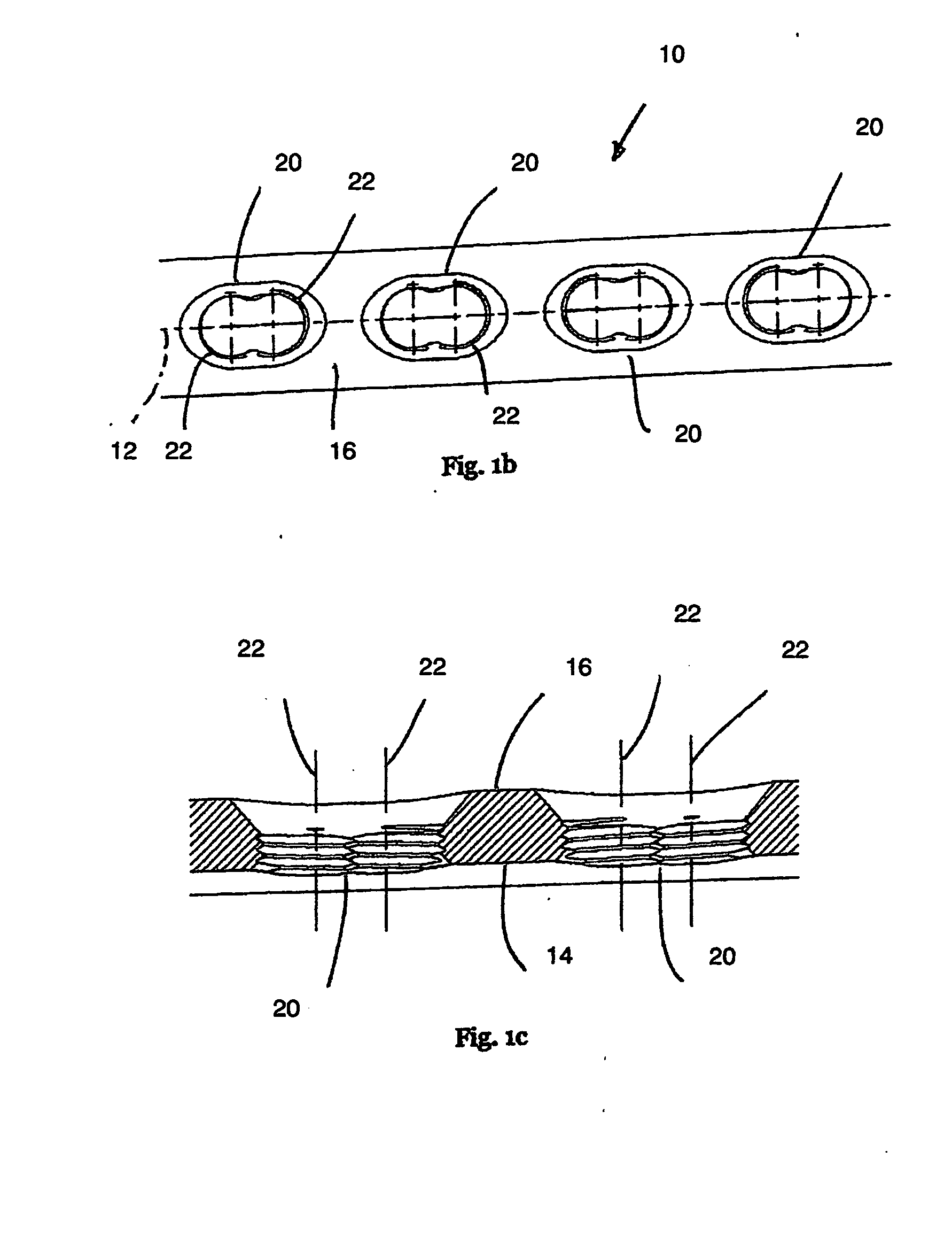
[0042] Referring now to FIGS. 1a to 1d, a bone plate 10 with a longitudinal axis 12 has a bone-contacting bottom side 14 and a top side 16. Multiple sets 20 of overlapping holes 22 communicate through the plate 10 from the top side 16 to the bottom side 14. The overlapping holes 22 are adapted to receive a bone screw 24 with a head 26 having a thread 30 and, on an opposite end 32, a body having a bone-engaging thread 34 (shown in FIG. 8).

[0043] The multiple sets 20 of overlapping holes 22 allow for further adjustability and flexibility in positioning of the bone plate 10 during surgery. The overlapping holes 22 are formed normal to the top side 16 of the plate 10 (shown in FIGS. 1c and 1d).

[0044] Referring now to FIGS. 2a and 2b, the overlapping holes 22 have multifaceted surfaces 36. In one embodiment, the multifaceted surface 36 is a threaded surface 40 (shown in FIG. 2a). In another embodiment, the multi-faceted surface 36 is a coaxial series of annular grooves 42 (shown in FIG...


PUM


Abstract

A bone plate with a longitudinal axis has a bone-contacting bottom side and a top side. Sets of overlapping holes communicate through the plate from the top to the bottom side. The overlapping holes have multifaceted surfaces such as a threaded surface or a coaxial series of annular grooves. The sets of overlapping holes are a adapted to receive a bone screw with a head and a bone-engaging thread.

Description

BACKGROUND OF THE INVENTION [0001] This invention relates to devices, implants and prostheses used in orthopedic surgery, and, more particularly, to bone plates used to reinforce fractured bones and thus promote healing. [0002] A compressive screw system, also known as the DCS system, is a bone plate system that has been used in trauma surgery for many years. The procedures for use of this system are well documented by the AO Institute, an institute having as one of its goals, the promotion of new orthopaedic surgical procedures. This system included a bone plate having slots communicating therethrough A land in which the slot is wider at one end defines a stepped surface adjacent the portion of the slot that extends through the bone plate. The stepped surface is generally cut with a spherical endmill, thus creating a spherical stepped surface. [0003] In a still further development, bone plates have been developed having individual threaded apertures and non-threaded apertures inter...

Claims


Application Information

Patent Timeline
IPC IPC(8): A61F2/30A61B17/17A61B17/80A61B19/02
CPCA61B17/1728A61B19/026A61B17/8057A61B17/8052A61B50/30A61B17/80A61B17/58
Inventor YOUNG, ROBERT ALLAN
Owner GREATBATCH MEDICAL SA
Why Eureka
Try Eureka