Multi-blade fan for air-cooled engine

a technology of air-cooled engines and blade fans, which is applied in the direction of liquid fuel engines, vessel construction, marine propulsion, etc., can solve the problems of increasing the number of components, increasing the cost, and less efficient and noisier than the turbofan, and achieves the effects of large air volume, less efficient and noisier, and small siz

Active Publication Date: 2006-12-07
HONDA MOTOR CO LTD
View PDF6 Cites 5 Cited by
  • Summary
  • Abstract
  • Description
  • Claims
  • Application Information

AI Technical Summary

Benefits of technology

[0003] While the multi-blade fan is characterized by small size and large air volume, it has a drawback in the point of being less efficient and noisier than the turbofan, another type of centrifugal fan. This led to the practice of lining the impeller cover with acoustic material or sound insulation material so

Problems solved by technology

While the multi-blade fan is characterized by small size and large air volume, it has a drawback in the point of being less efficient and noisier than the turbofan, another type of centrifugal fan.
Thus, the conventional approach to the noise problem has not focused on reducing the noise generated by the multi-blade fan but on adding members for suppressing propagation of the generated noise and, as such, has increased the number of components and raised cost.
Multi-blade fan noise consists of rotational nois

Method used


Image

  • Multi-blade fan for air-cooled engine
  • Multi-blade fan for air-cooled engine
  • Multi-blade fan for air-cooled engine

Examples


Embodiment Construction

[0021] A multi-blade fan for an air-cooled engine according to a preferred embodiment of the present invention will now be explained with reference to the attached drawings.

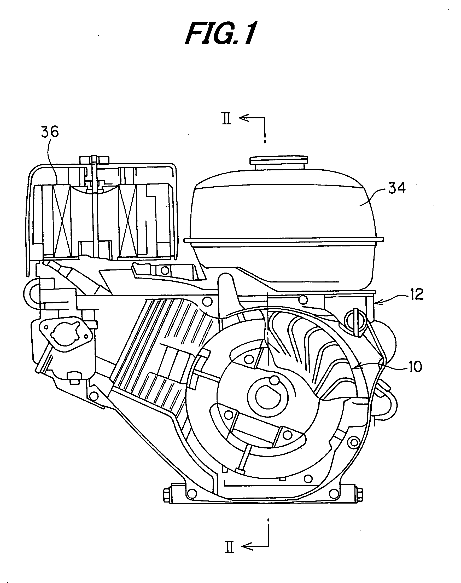
[0022]FIG. 1 is a side view showing the multi-blade fan for an air-cooled engine according to the preferred embodiment of the invention together with the engine it is attached to.

[0023] The reference numeral 10 in FIG. 1 designates the multi-blade fan for an air-cooled engine. The multi-blade fan 10 is attached to an air-cooled internal combustion engine 12. The engine 12 is a four-stroke, single-cylinder engine with a displacement of 196 cc.

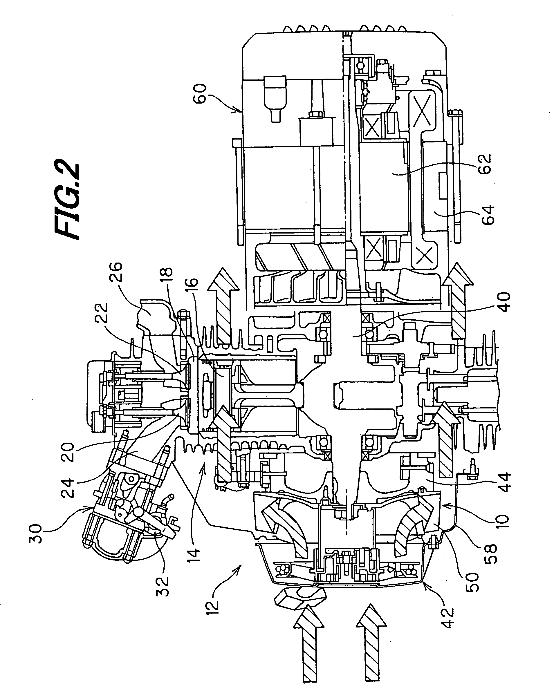
[0024]FIG. 2 is a sectional view taken along II-II in FIG. 1.

[0025] The engine 12 has a cylinder 14 accommodating a piston 16 that can reciprocate therein. An intake valve 20 and an exhaust valve 22 are provided to face into a combustion chamber 18 of the engine 10 for opening and closing communication of the combustion chamber 18 with an intake pipe 24 and an exhaust pip...


PUM


Abstract

In a multi-blade fan for an air-cooled engine, by defining the inlet angle β1 and the angle β′2 to make the sum thereof less than 80° (preferably defining β1 as 32° and β′2 as 36°), the multi-blade fan achieves greater air volume than in the case where the sum is made 80° or greater, where β1 is the angle between the relative velocity direction and the peripheral direction on the inlet side of the blades,β2 is the angle between the relative velocity direction and the peripheral direction on the outlet side of the blades, and β′2 is the difference obtained by subtracting β2 from 180°. The number of blades can therefore be reduced to realize lower noise level while still maintaining the same air volume as the prior art multi-blade fan.

Description

FIELF OF THE INVENTION [0001] This invention relates to a multi-blade fan for an air-cooled engine, particularly to a multi-blade fan for an air-cooled engine that cools an internal combustion engine with cooling air blown onto the engine by rotating an impeller having many forward-curved blades. DESCRIPTION OF THE RELATED ART [0002] Owing to its small size and large air volume, the multi-blade fan (sirocco fan) has come to be widely used as a fan for forcefully blowing cooling air onto an engine. The multi-blade fan is a kind of centrifugal fan that blows air by rotating an impeller having many forward-curved blades. An example of such a fan can be found in Japanese Laid-Open Patent Application No. 2001-271791. SUMMARY OF THE INVENTION [0003] While the multi-blade fan is characterized by small size and large air volume, it has a drawback in the point of being less efficient and noisier than the turbofan, another type of centrifugal fan. This led to the practice of lining the impell...

Claims


Application Information

Patent Timeline
IPC IPC(8): B63H1/16
CPCF04D29/666F04D29/281
Inventor HATSUGAI, TSUTOMUIDEGUCHI, TAKAHIROTABATA, YUTAKA
Owner HONDA MOTOR CO LTD
Why Eureka
Try Eureka