Electronic security device

a security device and electronic technology, applied in anti-theft devices, instruments, program control, etc., can solve the problems of time-consuming opening, lock must be removed by other less convenient methods, additional inconvenience and expense,

Inactive Publication Date: 2006-12-21
MASTER LOCK CO INC
View PDF40 Cites 87 Cited by
  • Summary
  • Abstract
  • Description
  • Claims
  • Application Information

AI Technical Summary

Benefits of technology

[0004] The present application relates to the operation of a security device or lock, such as, for example, a padlock, through the use of a motor operated locking arrangement. The lock may utilize a variety of arrangements for providing an authorized signal to operating the locking arrangement, including, for example, use of a key or other instrument provided with electronic circuitry for communicating with the lock, use of a keypad for entry of an authorization code, or use of a remote signal transmitter and corresponding receiver or detector on the lock to remotely transmit an input signal with authorization code to the lock for operation. In one embodiment, one of various remote signaling mechanisms may be used, such as, for example, an infrared (IR) signaling mechanism or a radio transmitter. In an exemplary embodiment, a transmitter is adapted to send a signal to a r...

Problems solved by technology

Locks that are opened by a combination require the operator to remember a series of numbers or symbols, and in some cases may be time consuming to open.
If the operator cannot remember the combination, the lock must be removed by other less convenient methods, such as, for example, by a bolt cutter.
In such a case, the damaged lock must be replaced, resulting ...

Method used


Image

  • Electronic security device
  • Electronic security device
  • Electronic security device

Examples


Embodiment Construction

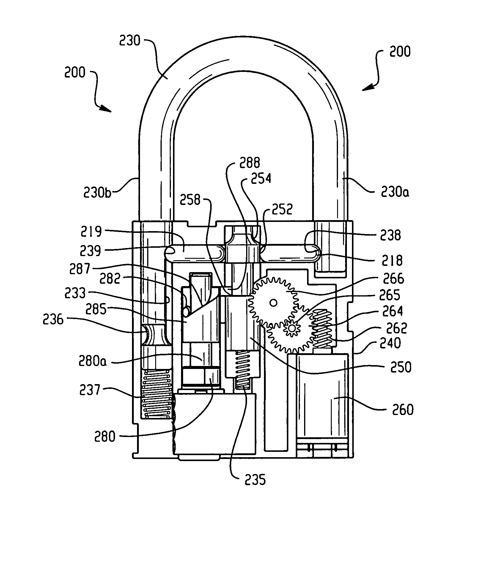
[0023] This Detailed Description merely describes embodiments of the invention and is not intended to limit the scope of the claims in any way. Indeed, the invention as described by the claims is broader than and unlimited by the preferred embodiments, and the terms in the specification have their full ordinary meaning.

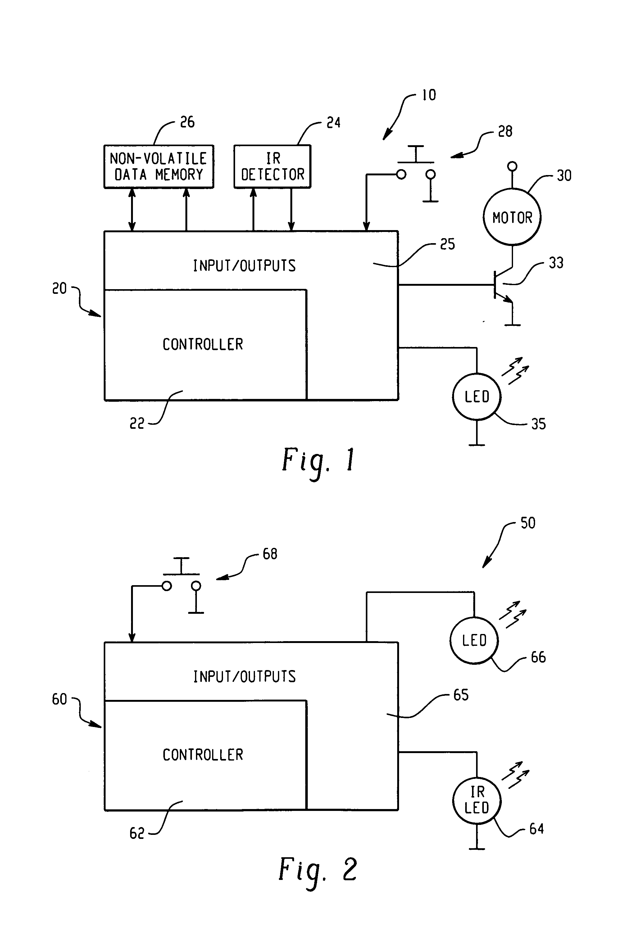
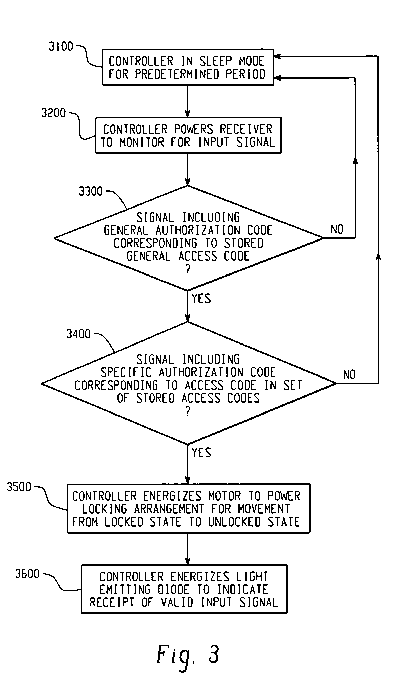
[0024] The present invention provides a security device, such as a padlock, adapted for direct or remote electronic operation in unlocking the device to access a locked item, such as a room, building, container, or piece of equipment, with which the security device is installed. In one embodiment of the invention, a remote signal transmitter is provided to transmit an input signal, such as, for example, an infrared (IR) or radio signal, to a receiver on the lock for operation of a locking arrangement. The receiver transmits the signal to a logic applying arrangement within the lock for energizing the locking arrangement to move from a locked state to an unlocked stat...


PUM


Abstract

A lock is provided with a housing, a shackle movably coupled to the housing, and a locking arrangement movable between a locked state and an unlocked state. The lock includes a receiver arranged to receive a remote input signal including at least one authorization code. The lock includes a logic applying arrangement programmed to selectively store at least one access code responsive to a corresponding authorization code received by the receiver and to energize the locking arrangement to move from the locked state to the unlocked state when an authorization code received by the receiver corresponds with one of a set of stored access codes. The locking arrangement is configured to secure the shackle within the housing when the locking arrangement is in the locked state, and the locking arrangement is configured to allow the shackle to move relative to the housing when the locking arrangement is in the unlocked state.

Description

CROSS REFERENCE TO RELATED APPLICATIONS [0001] This application claims the benefit of U.S. Provisional Patent Application No. 60 / 685,860, filed May 31, 2005. This application also claims the benefit of U.S. Provisional Patent Application No. 60 / 728,931, filed Oct. 20, 2005. The entire disclosures of both applications are hereby incorporated by reference.FIELD OF THE INVENTION [0002] The present invention relates generally to an electronic security device, and more specifically to an electronically operated padlock. BACKGROUND OF THE INVENTION [0003] Security devices, such as, for example, padlocks and other types of conventional locks are known in the art, used, for example, to prevent access to a room, building, container, or piece of equipment. Exemplary padlocks include those opened by a key and those opened by manipulation of lock components in accordance with a unique combination. Locks that are opened by a combination require the operator to remember a series of numbers or sym...

Claims


Application Information

Patent Timeline
IPC IPC(8): E05B67/24
CPCE05B2047/0026E05B2047/0034E05B2047/0058E05B2047/0065E05B2047/0094G07C9/00182E05B2047/0024G07C9/00896G07C2009/00769G07C2009/00849E05B47/0012E05B67/24E05B2047/002G07C9/00817Y10T70/459
Inventor MARCELLE, JESSE A.MEEKMA, GLENNLESLIE, VINCE
Owner MASTER LOCK CO INC
Why Eureka
Try Eureka