
Power Management for Battery Powered Appliances

a battery-powered appliance and power management technology, applied in electric vehicles, ac-dc conversion without reversal, transportation and packaging, etc., can solve the problems of high battery charging algorithm, long charge time, high cost, etc., and achieve the effect of reducing power topologies

Inactive Publication Date: 2006-12-28
O2 MICRO INT LTD
View PDF5 Cites 17 Cited by
  • Summary
  • Abstract
  • Description
  • Claims
  • Application Information

AI Technical Summary

Benefits of technology

[0016] Accordingly, the present invention provides a power management topology that includes an external AC / DC adapter that is controlled by battery charge controller. In the exemplary embodiments, the charge controller includes the error amplifiers to generate a feedback control signal, while the AC / DC adapter is modified to receive the control feedback signal to regulate the duty cycle of the PWM generator associated with the adapter. Thus, in the exemplary embodiments, the need for a PWM generator and controller, as well as power switches and a DC / DC converter are eliminated in the charger circuit, thereby economizing power topologies, as well as removing heat-generating portions of a conventional battery charger circuit to the external AC / DC adapter.

Problems solved by technology

Hence the benefits are small size and light weight, highly valued by travelers, but may cost more than other types of adapters.
The battery charging algorithm is highly compromised, resulting in long charge times, perhaps never reaching full charge and limited ability to adapt to multiple battery chemistries like LiIon, NiMH and NiCd.
The wasted power is dissipated within the regulator increasing the temperature within the small, tightly enclosed product.
Additionally the wasted power significantly shortens the battery life which is of paramount importance to anyone carrying these products around.
The negatives include short battery life and high internal temperatures.
Benefits of this type of design are rapid charging, high efficiency and adaptability to varying adapters and battery chemistries, but may cost more than linear regulators.
Additionally, an error amplifier may be included to monitor input power availability and generate an error signal if the available power from the adapter 12 is exceeded.

Method used


Image

  • Power Management for Battery Powered Appliances
  • Power Management for Battery Powered Appliances
  • Power Management for Battery Powered Appliances

Examples


Embodiment Construction

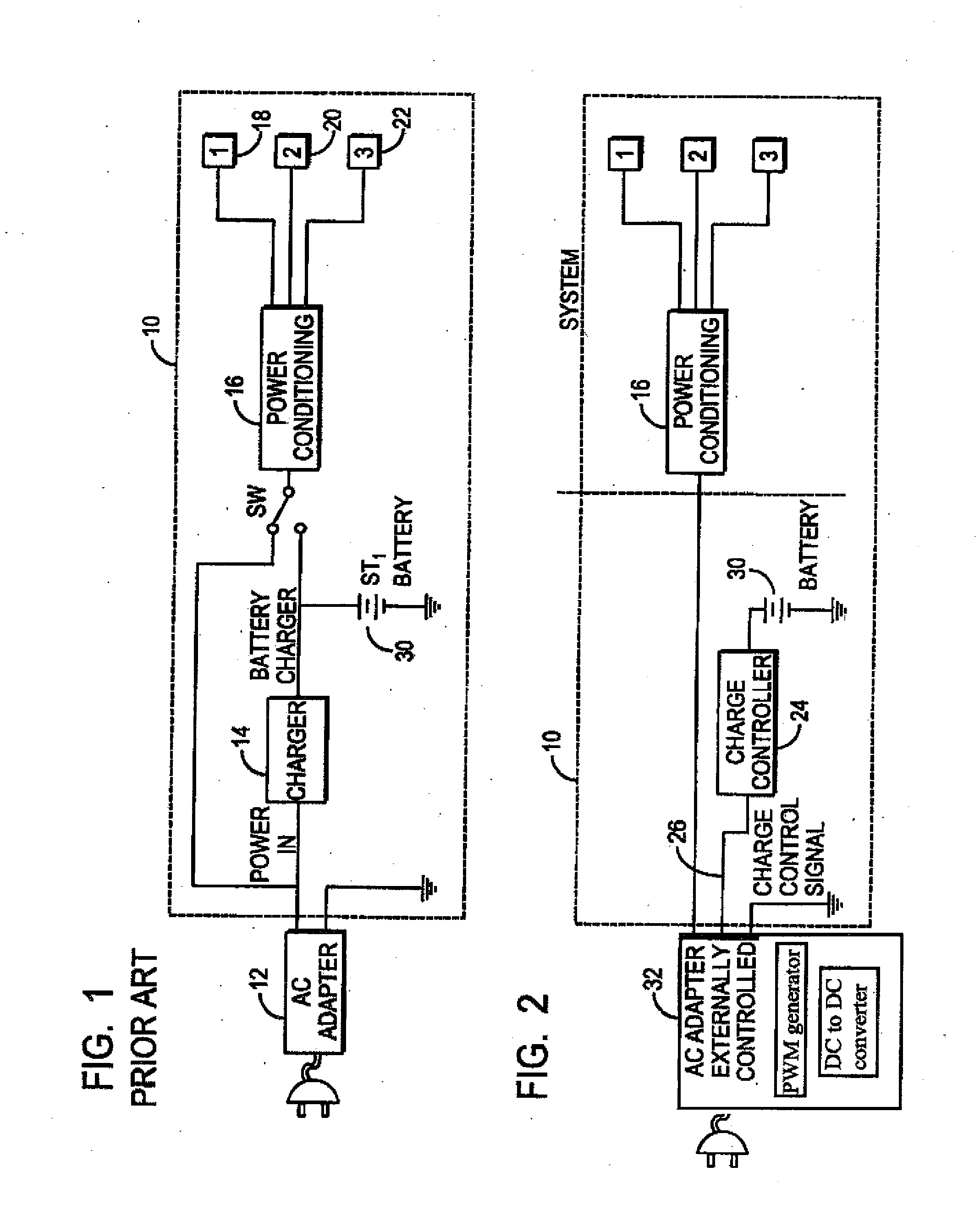
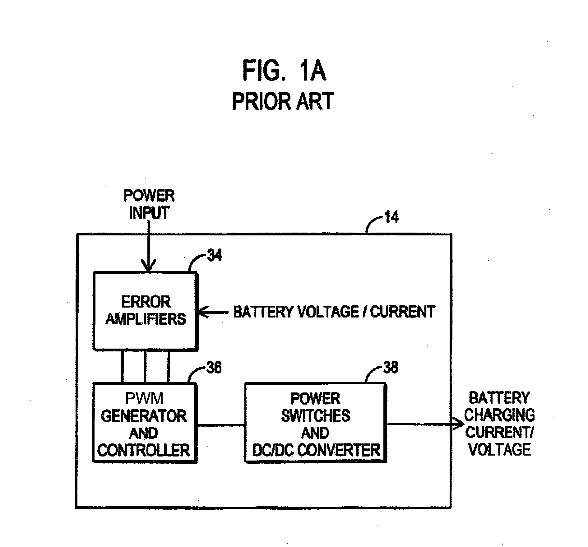
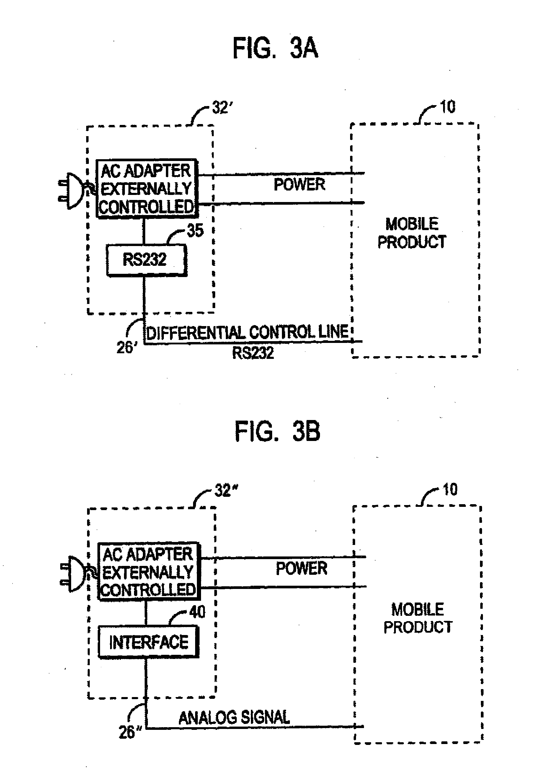
[0025]FIG. 2 depicts a block diagram of an exemplary power management topology according to the present invention. As with the conventional power management topology of FIG. 1, the topology of FIG. 2 includes a system 10 powered by an AC / DC adapter 32. However, in this exemplary embodiment, the adapter 32 is feedback enabled to receive one or more feedback control signals generated by the error amplifiers associated with the charger. Thus, in this exemplary embodiment, it is only necessary for the charger to include error amplifiers, and is thus generalized as a charge controller 24. The charge controller 24 includes a plurality of error amplifiers that monitor battery voltage and / or current and generate an error signal if the battery voltage and / or current exceed some predetermined threshold. Additionally, an error amplifier may be included to monitor input power availability and generate an error signal based on the charging requirement of the battery balanced with the power requi...


PUM


Abstract

A power management topology for portable electronic devices that includes a feed-enabled AC / DC adapter that receives feedback data from a charge controller associated with the portable device. The feedback data can include battery charging current, battery voltage, or power requirements of the portable device. Using the feedback data, the external AC / DC adapter can adjust the DC output to meet the charging requirement of the battery and / or the power requirements of the portable device.

Description

CROSS REFERENCE TO RELATED APPLICATIONS [0001] This application is a Continuation of U.S. Nonprovisional application Ser. No. 10 / 685,043 filed Oct. 14, 2003, now U.S. Pat. No. 7,088,076, which itself is a Continuation of U.S. Nonprovisional application Ser. No. 09 / 960,453 filed Sep. 21, 2001, now U.S. Pat. No. 6,741,066, which all claim the benefit of U.S. Provisional Application Ser. No. 60 / 234,442, filed Sep. 21, 2000, the teachings of which are incorporated herein by reference.BACKGROUND OF THE INVENTION [0002] 1. Field of the Invention [0003] The present invention relates to power management for battery powered devices, and more particularly, to a power management topology that includes an external AC / DC adapter that is controlled by battery charge controller associated with a portable device. [0004] 2. Background Description [0005] Present battery charging topologies are divided into two separate designs and implementation: AC adapters and battery charging topologies. [0006] AC...

Claims


Application Information

Patent Timeline
Patent Type & Authority Applications(United States)
IPC IPC(8): H02M7/02H02J7/04
CPCH02J7/045H02J7/04H02J7/00714H02J7/007182
Inventor DENSHAM, WILLIAM L.POPESCU-STANESTI, VLAD MIHAILSPIRIDON, CONSTANTIN
Owner O2 MICRO INT LTD
Learn More