System and method for controlling network traffic

a network traffic and network traffic technology, applied in the field of system for controlling a network traffic path, can solve the problems of many inefficient and unreasonable situations, forced to use an inefficient flooding path, and use an optimized switching path

Inactive Publication Date: 2006-12-28
CHO CHANG HWAN +1
View PDF5 Cites 98 Cited by
  • Summary
  • Abstract
  • Description
  • Claims
  • Application Information

AI Technical Summary

Benefits of technology

The patent describes a switching control module that is mounted on each switch and can communicate with other switches in real-time. The module can exchange information about the status of the switches and use this information to select the best port for forwarding network traffic. This allows for efficient control of network traffic and can improve the overall performance of the network.

Problems solved by technology

The technical problem addressed in this patent text is the inefficient and unreasonable use of switches in a network due to the single root switch based topology, which results in unbalanced switching paths, delays in activation of alternate ports, and vulnerability to security infringements. Additionally, the root switch based topology prevents the use of redundant paths for forwarding frames.

Method used


Image

  • System and method for controlling network traffic
  • System and method for controlling network traffic
  • System and method for controlling network traffic

Examples


Embodiment Construction

[0044] Hereinafter, a preferred embodiment of the present invention will be described with reference to the accompanying drawings. In the following description of the present invention, a detailed description of known functions and configurations incorporated herein will be omitted when it may make the subject matter of the present invention rather unclear.

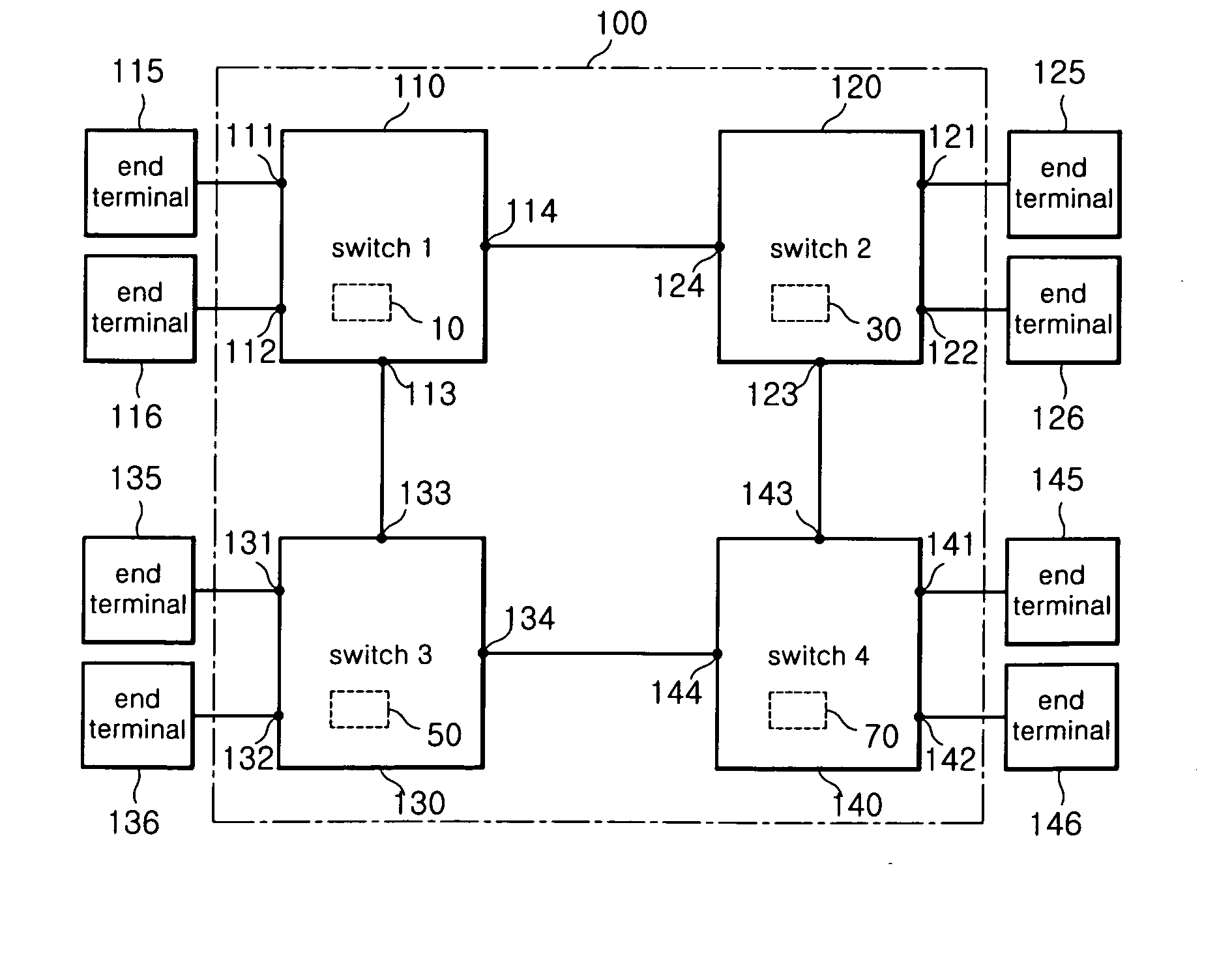
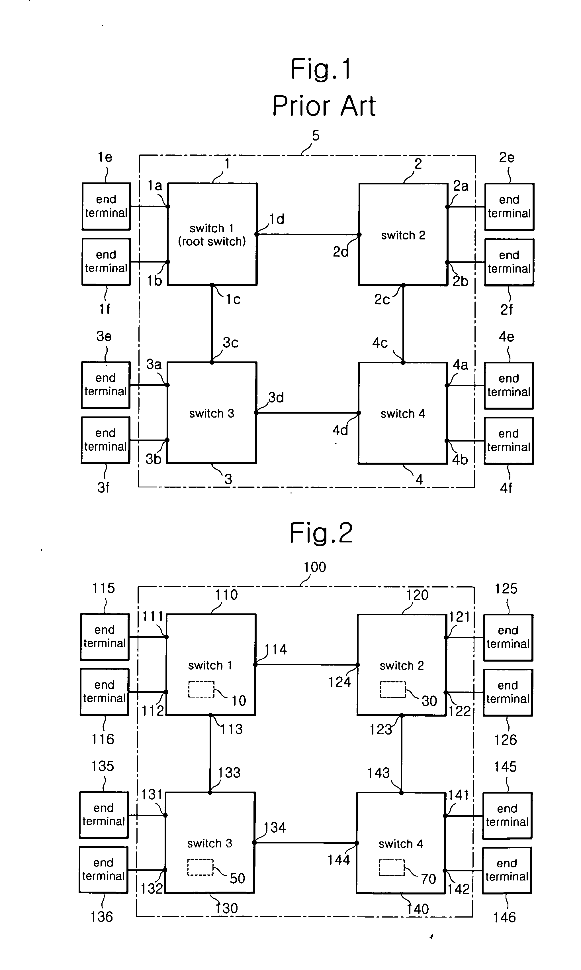
[0045] As shown in FIG. 2, a network traffic controlling system 100 according to an embodiment of the invention is a systematically structured system comprising multiple switches 110, 120, 130, 140 connected to each other and multiple end terminals 115, 116, 125, 126, 135, 136, 145, 146 arrangedto eachofthe switches 110, 120, 130, 140.

[0046] At this time, ports 111, 112, 121, 122, 131, 132, 141, 142 each connects end terminals 115, 116, 125, 126, 135, 136, 145, 146 to switches 110, 120, 130, 140, and ports 113, 114, 123, 124, 133, 134, 143, 144 each connects other switches.

[0047] Hereinafter, for convenience sake, it is assumed...


PUM


Abstract

Disclosed are system and method for controlling a network traffic. According to the invention, all switches connected with the same VLAN are allowed to share an inherent ID of each switch, a port ID connecting the switches and information about a bandwidth so as to calculate an optimized path that each switch is connected to other switches. For doing so, each switch is systematically structured to comprise a computation module capable of structuring a neighbor relation with other switches, a computation module capable of exchanging/sharing the switch state D/B with the other switches, and synchronizing a corresponding switch state D/B, a computation module capable of creating/updating a switching table, and a computation module capable of switching and flooding a received data frame through an optimized path with reference to the created/updated switching table.

Description


Claims


Application Information

Patent Timeline
Owner CHO CHANG HWAN
Why Eureka
Try Eureka