Self-sufficient energy lighting device

a self-sufficient, energy-saving technology, applied in the direction of dynamo-electric machines, dynamo-electric components, vehicle components, etc., can solve problems such as potential dangers

Inactive Publication Date: 2007-01-04
CHIANG HAN CHUNG
View PDF6 Cites 11 Cited by
  • Summary
  • Abstract
  • Description
  • Claims
  • Application Information

AI Technical Summary

Problems solved by technology

To conserve electrical energy and hold down production costs, sides of automobiles and other vehicles often have no lights so people have difficulty seeing those vehicles from their sides at night, which causes a potentially hazardous condition to exist.

Method used


Image

  • Self-sufficient energy lighting device
  • Self-sufficient energy lighting device
  • Self-sufficient energy lighting device

Examples


Embodiment Construction

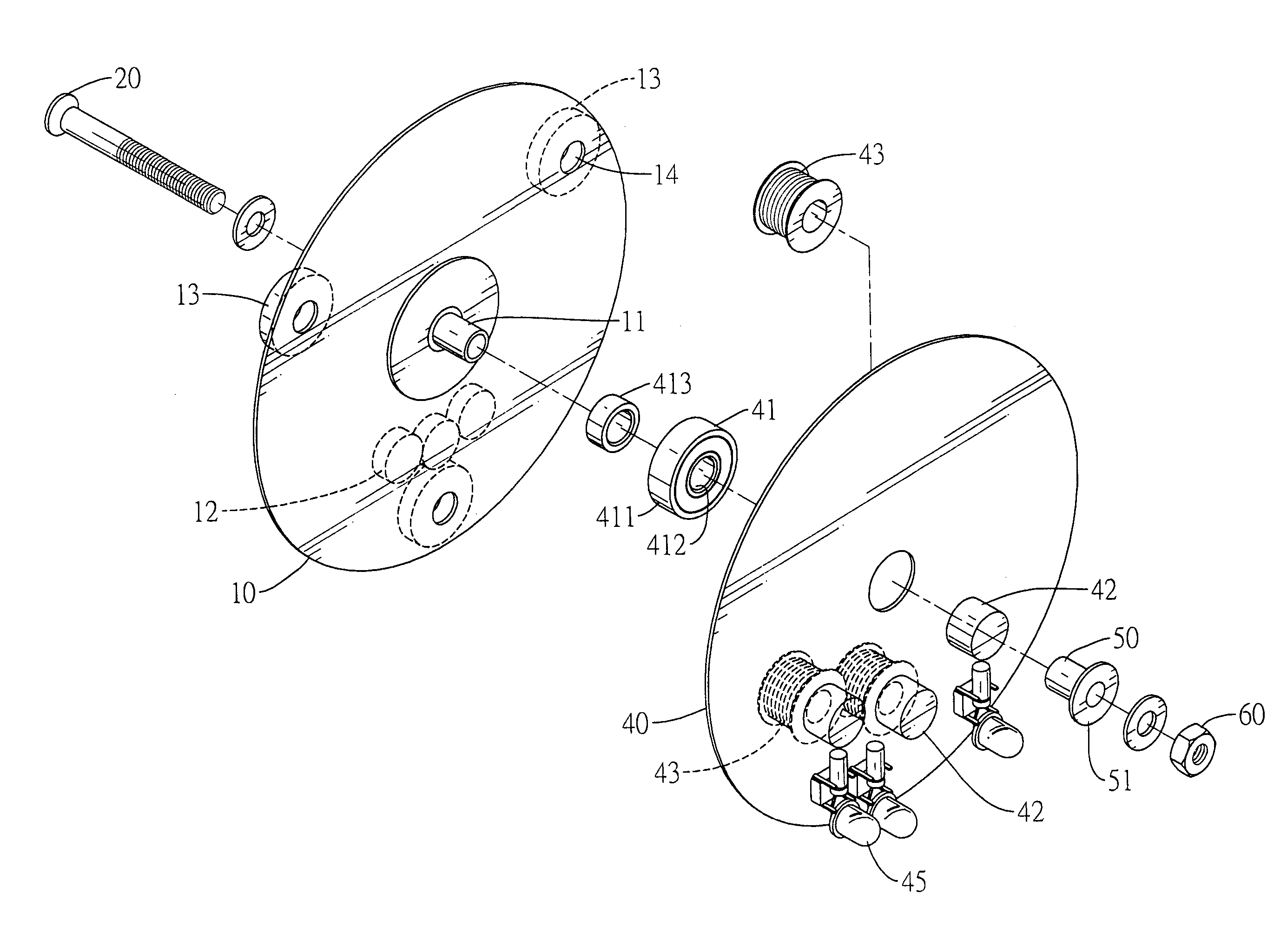
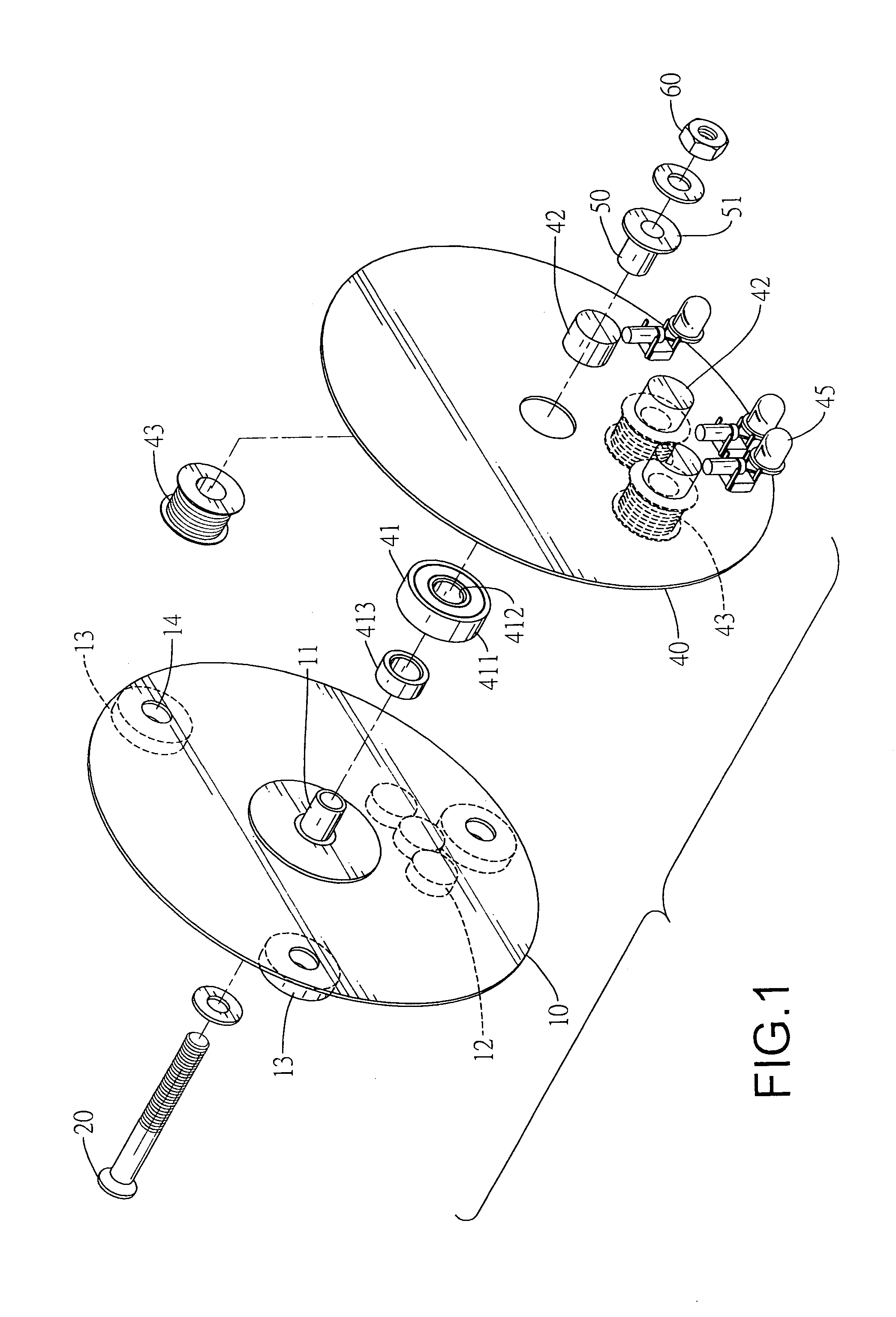
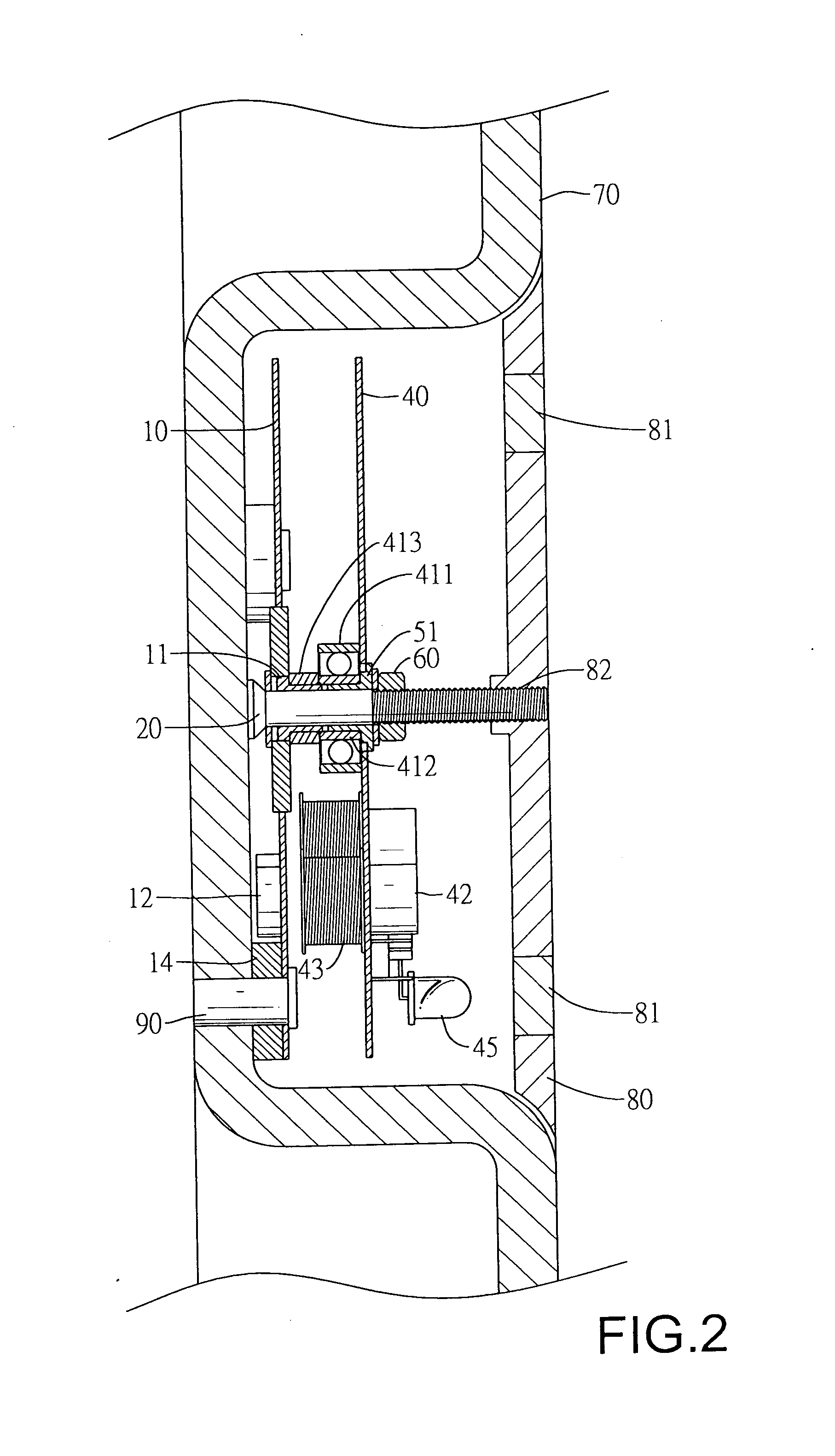
[0016] With reference FIGS. 1 and 2, a self-sufficient energy lighting device in accordance with the present invention is mounted securely on a wheel hub (70). The wheel hub (70) is mounted on a vehicle and has multiple threaded holes defined through the wheel hub (70).

[0017] The self-sufficient energy lighting device comprises a first disk (10), a pivot pin (20), a second disk (40), a mounting sleeve (50), a nut (60) and a hubcap (80).

[0018] The first disk (10) is attached securely to the wheel hub (70) and has an outer surface, an inner surface, an axis, multiple mounting holes (14), multiple resilient gaskets (13), a central sleeve (11) and at least one magnet (12). The mounting holes (14) are defined through the first disk (10) and correspond to the threaded holes in the wheel hub (70). The first disk (10) is attached to the wheel hub (70) by multiple fasteners (90) such as bolts extending respectively through the mounting holes (14) in the first disk (10) and screwing into th...


PUM


Abstract

A self-sufficient energy lighting device is mounted on a vehicle wheel hub and has a first disk, a pivot pin, a second disk, a nut and hubcap. The first disk is attached securely to the wheel hub has at least one magnet. The pivot pin extends out through the first disk. The second disk is rotatably mounted on the pivot pin and has at least one coil and at least one lighting element electrically connected to the coil. When the vehicle runs and turns the wheel hub and first disk, the second disk rotates relative to the first disk and causes the lighting element to shine.

Description

BACKGROUND OF THE INVENTION [0001] 1. Field of the Invention [0002] The present invention relates to a lighting device, and more particularly to a self-sufficient energy lighting device that is mounted on a rotating wheel of a vehicle without an external power source. [0003] 2. Description of Related Art [0004] Most vehicles intended for street use must have headlights, taillights and turn signals mounted on the front and rear of vehicles so that the lights and signals shine and warn people nearby. [0005] To conserve electrical energy and hold down production costs, sides of automobiles and other vehicles often have no lights so people have difficulty seeing those vehicles from their sides at night, which causes a potentially hazardous condition to exist. [0006] To overcome the shortcomings, the present invention provides a self-sufficient energy lighting device to mitigate or obviate the aforementioned problems. SUMMARY OF THE INVENTION [0007] The main objective of the invention is...

Claims


Application Information

Patent Timeline
Patent Type & Authority Applications(United States)
IPC IPC(8): B60Q1/26
CPCH02K7/1846B60Q1/326
Inventor CHIANG, HAN-CHUNG
Owner CHIANG HAN CHUNG
Why Eureka
Try Eureka