
Hybrid voltage/current-mode transmission line driver

a transmission line and current-mode technology, applied in the direction of digital transmission, line-transmission details, duplex signal operation, etc., can solve the problems of data loss, impedance mismatch with characteristic impedance, and communication channels used to transfer data between system components is rapidly becoming a bottleneck, so as to compensate frequency-dependent losses, sacrificing impedance matching, and avoiding significant power consumption

Active Publication Date: 2007-01-04
APPLE INC
View PDF2 Cites 71 Cited by
  • Summary
  • Abstract
  • Description
  • Claims
  • Application Information

AI Technical Summary

Benefits of technology

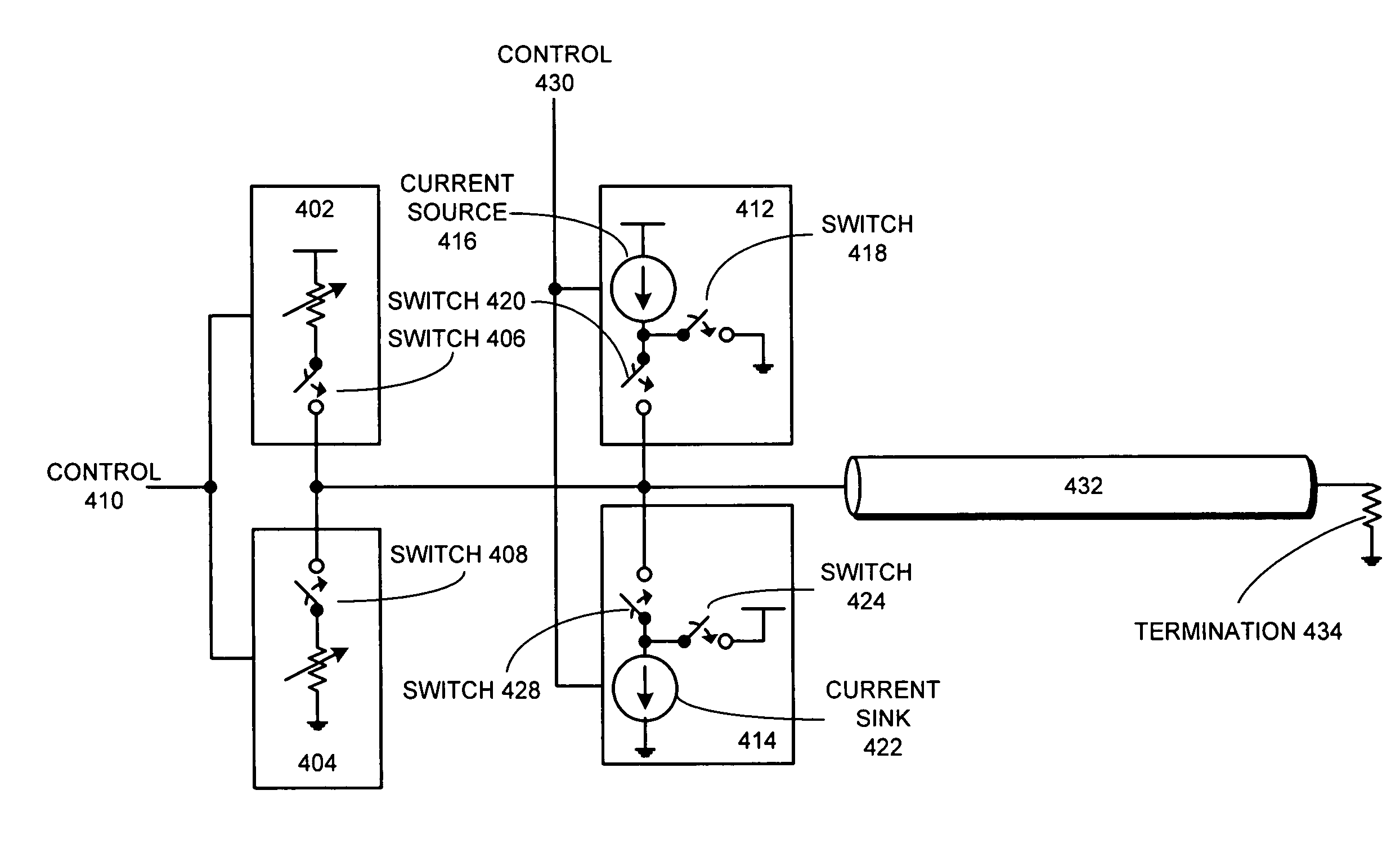
[0010] One embodiment of the present invention provides a system that transmits signals through a communication channel. During operation, the system receives a sequence of bits for transmission through the communication channel. While transmitting a given bit, the system determines if the given bit has the same state as the previously transmitted bit. If so, the system uses a voltage-mode driver to drive a signal through the communication channel. Otherwise, the system uses a current source coupled to the voltage-mode driver to boost the drive-level of the voltage-mode driver. Note that the current source supplies a current to the communication channel without changing the impedance of the voltage-mode driver. In this way, the present invention compensates for frequency dependant losses in the communication channel without sacrificing impedance matching and without substantially increasing power consumption. Note that this configuration saves power because the current source does not consume any power when it is turned off (i.e. when the given bit is the same as the previously transmitted bit).
[0011] In a variation on this embodiment, the current source is activated independently from the voltage-mode driver, thereby facilitating the optimization of the shape of the transmitted signal.
[0012] In a variation on this embodiment, more than one current source is used to compensate for frequency dependant losses in the communication channel. Furthermore, each current source is activated separately from the other current sources as well as the voltage-mode driver, thereby facilitating the optimization of the shape of the transmitted signal.
[0013] In a variation on this embodiment, a sequence of previously transmitted bits is used to control the current source to compensate for the frequency dependant losses in the communication channel.

Problems solved by technology

However, as the frequency of these systems increases, the communication channels used to transfer data between system components is rapidly becoming a bottleneck.
Consequently, if the system transmits data through the communication channel at a sufficiently high frequency, data can be lost.
Unfortunately, boosting the drive strength in a voltage-mode driver also involves decreasing the source resistance of the driver, which can cause an impedance mismatch with the characteristic impedance of the communication channel.
Hence, a voltage-mode driver cannot compensate for these frequency-dependent losses without causing a corresponding impedance mismatch.
Unfortunately, a current-mode driver uses significantly more power than the voltage-mode driver, which makes such drivers impractical for many applications.

Method used


Image

  • Hybrid voltage/current-mode transmission line driver
  • Hybrid voltage/current-mode transmission line driver
  • Hybrid voltage/current-mode transmission line driver

Examples


Embodiment Construction

[0026] The following description is presented to enable any person skilled in the art to make and use the invention, and is provided in the context of a particular application and its requirements. Various modifications to the disclosed embodiments will be readily apparent to those skilled in the art, and the general principles defined herein may be applied to other embodiments and applications without departing from the spirit and scope of the present invention. Thus, the present invention is not limited to the embodiments shown, but is to be accorded the widest scope consistent with the principles and features disclosed herein.

Voltage-Mode Drivers

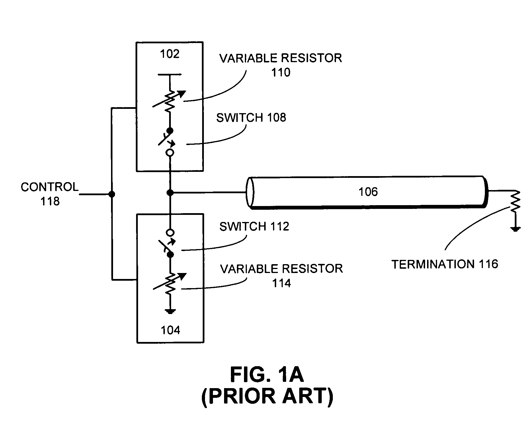
[0027]FIG. 1A presents a block diagram of a voltage-mode driver. It contains pull-up network 102, pull-down network 104, communication channel 106, switches 108 and 112, variable resistors 110 and 114, termination 116, and control signal 118.

[0028] When the voltage-mode driver transmits a high bit, control signal 118 closes switch 108...


PUM


Abstract

A system that transmits signals through a communication channel. During operation, the system receives a sequence of bits for transmission through the communication channel. While transmitting a given bit, the system determines if the given bit has the same state as the previously transmitted bit. If so, the system uses a voltage-mode driver to drive a signal through the communication channel. Otherwise, the system uses a current source coupled to the voltage-mode driver to boost the drive-level of the voltage-mode driver. Note that the current source supplies a current to the communication channel without changing the impedance of the voltage-mode driver. In this way, the present invention compensates for frequency dependant losses in the communication channel without sacrificing impedance matching and without substantially increasing power consumption.

Description

BACKGROUND [0001] 1. Field of the Invention [0002] The present invention relates to techniques for communicating data through a communication channel. More specifically, the present invention relates to a method and apparatus for compensating for frequency dependent losses when transmitting signals through a lossy communication channel. [0003] 2. Related Art [0004] Advances in semiconductor fabrication technology presently make it possible to integrate large-scale systems, including tens of millions of transistors, into a single semiconductor chip. Integrating such large-scale systems onto a single semiconductor chip enables increases in the frequency at which such systems can operate, because signals between system components do not have to cross chip boundaries, and are not subject to lengthy chip-to-chip propagation delays. [0005] However, as the frequency of these systems increases, the communication channels used to transfer data between system components is rapidly becoming a ...

Claims


Application Information

Patent Timeline
Patent Type & Authority Applications(United States)
IPC IPC(8): H04B3/00
CPCH04B3/04
Inventor CORNELIUS, WILLIAM P.HERNDON, MATTHEW K.LARSON, RONALD K.
Owner APPLE INC
Learn More