Dynamic non-linear display

Active Publication Date: 2007-01-04
MARINVENT CORP
View PDF2 Cites 11 Cited by
  • Summary
  • Abstract
  • Description
  • Claims
  • Application Information

AI Technical Summary

Benefits of technology

[0020] According to another aspect of the invention there is provided a method for displaying a dynamic parameter, the method comprising providing a reading of the dynamic parameter, generating a scale having scale ends, the scale changing dynamically and non-linearly using the provided reading of the dynamic parameter and a selected display algorithm signal together with a minimum dynamic parameter value and a maximum dynamic parameter value, and a pointer pointing to the scale in accordance with the reading of the dynamic parameter and displaying the scale, the minimum dynamic parameter value and the maximum dynamic parameter value, such that the selected display algorithm constantly and exactly fits the reading, and the

Problems solved by technology

Measurement and displaying of dynamic parameters of an aircraft is a key issue for properly controlling, managing and validating aircraft position and velocity.
This format is difficult to interpret, particularly during dynamic situations.
Use of this technology resulted in several aircraft accidents because the small 10,000 ft pointer is easily obscured by larger pointers, leading to interpretation errors of multiples of 10,000 ft.
This tendency became unacceptable with the advent of jet aircraft, whose high rates of climb and descent rendered the three-pointer altimeter virtually useless.
This is because at high altitudes, neither the counter pointer nor the tape altimeter can show the zero-altitude d

Method used


Image

  • Dynamic non-linear display
  • Dynamic non-linear display
  • Dynamic non-linear display

Examples


first embodiment

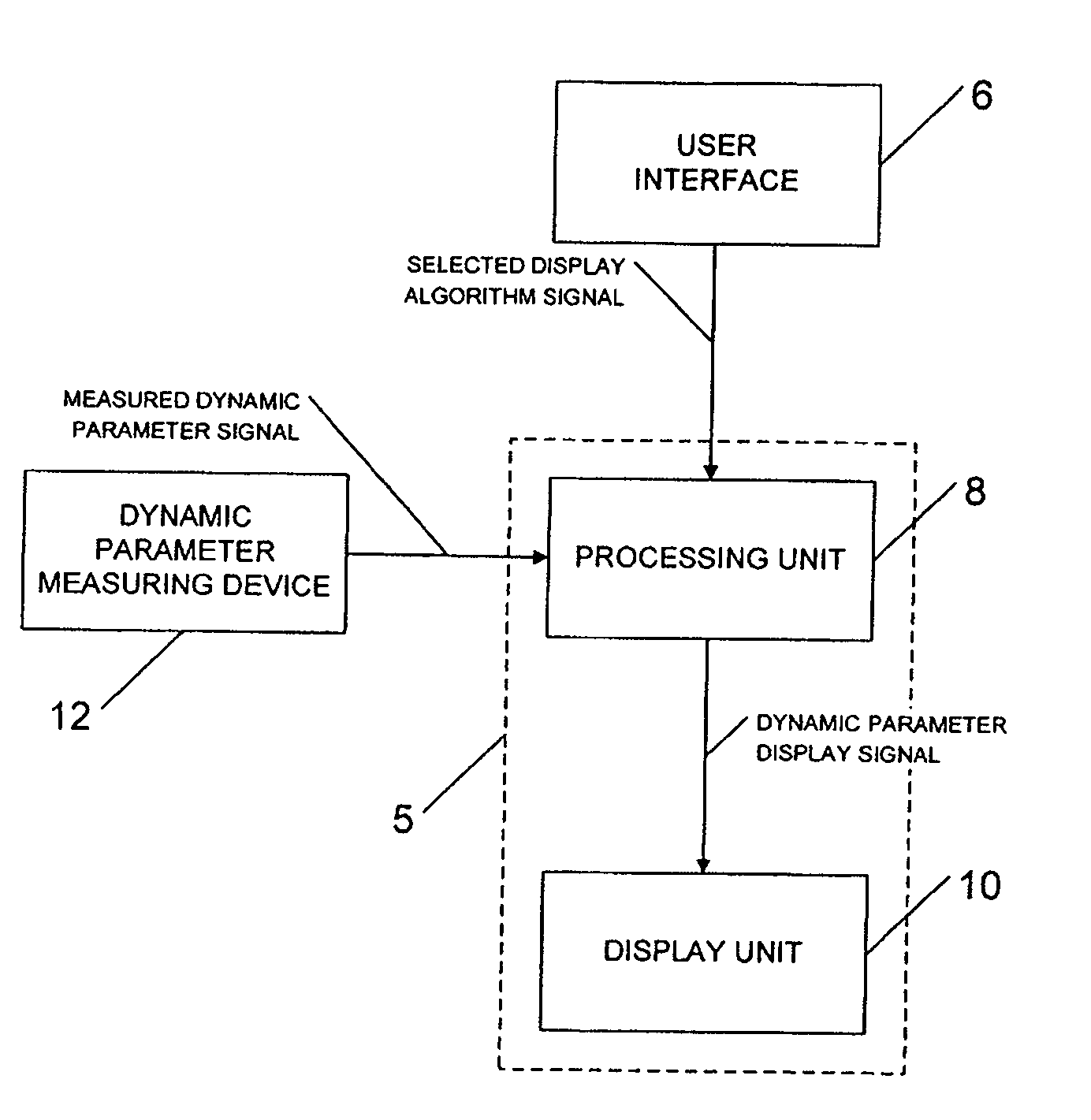
[0081] Now referring to FIG. 9, there is shown a block diagram which shows the invention where the electronic non-linear aircraft dynamic parameter display is an electronic non-linear aircraft altimeter display 118.

[0082] The electronic non-linear aircraft altimeter display 118 comprises a processing unit 112 and a display unit 114.

[0083] Still in this first embodiment of the invention, the processing unit 112 is an air data computer, which is well known to someone versed in the art, while the display unit 114 is either an Electronic Flight Instrument System (EFIS), a Multifunction Display (MFD), or a Head-Up Display (HUD), all of which are well known to someone versed in the art.

[0084] The processing unit 112 receives a selected display algorithm signal and an altitude reference signal provided by the user interface 110 and a measured altitude signal provided by the altitude measuring device 116.

[0085] The processing unit 112 provides an altitude display signal to the display un...

second embodiment

[0121] Now referring to FIG. 13, there is shown a block diagram which shows the invention where the electronic non-linear aircraft dynamic parameter display is an electronic non-linear aircraft speed display 162.

[0122] The electronic non-linear aircraft speed display 162 comprises a processing unit 164 and a display unit 166.

[0123] Still in this first embodiment of the invention, the processing unit 164 is an air data computer, which is well known to one versed in the art, while the display unit 166 is an airspeed display on an electronic Flight Instrumentation System (EFIS), a multifunction Display (MFD), or a Head-Up Display (HUD), all of which are well known to one versed in the art.

[0124] The processing unit 164 receives a selected display algorithm signal provided by the user interface 160 and a measured speed signal provided by the speed measuring device 168.

[0125] The processing unit 164 provides a speed display signal to the display unit 166.

[0126] Now referring to FIG. ...


PUM


Abstract

A method and apparatus is disclosed for displaying a dynamic parameter, the apparatus comprises a display unit receiving a display signal and displaying a scale that changes dynamically and non-linearly in accordance with a selected display algorithm, the display unit further displaying a pointer pointing to said scale in accordance with a reading of said dynamic parameter, thereby emphasizing a range of said reading of said dynamic parameter.

Description

CROSS-REFERENCE TO RELATED APPLICATIONS [0001] This patent application is a continuation-in-part of U.S. patent application Ser. No. 10 / 670,780 filed on Sep. 26, 2003 which claims priority from U.S. provisional patent application No. 60 / 415,807, entitled “Electronic non-linear aircraft altitude and vertical speed display”, filed on Oct. 4, 2002, the specifications of which are hereby incorporated by reference.TECHNICAL FIELD [0002] This invention relates to the field of instruments. More precisely, this invention relates to dynamic non-linear displays. BACKGROUND OF THE INVENTION [0003] Measurement and displaying of dynamic parameters of an aircraft is a key issue for properly controlling, managing and validating aircraft position and velocity. [0004] It is known that measurement of aircraft altitude and vertical speed, by barometric and other means, is a mature technology which is founded on principles which have remained relatively unchanged since the first deployment of altimeter...

Claims


Application Information

Patent Timeline
IPC IPC(8): G06F19/00G01D7/00
CPCG01D7/00G01C23/00
Inventor MARIS, JOHN
Owner MARINVENT CORP
Why Eureka
Try Eureka