Data transmission method and a system thereof

a data transmission and data technology, applied in the field of data transmission methods and their systems, can solve the problems of difficult to realize optical plls, complicated filter control systems, and difficulty in meeting changes in modulation methods, and achieve the effect of high-sensitivity receiving levels and faster data rates

Inactive Publication Date: 2007-01-11
NAT INST OF INFORMATION & COMM TECH
View PDF4 Cites 12 Cited by
  • Summary
  • Abstract
  • Description
  • Claims
  • Application Information

AI Technical Summary

Benefits of technology

[0011] Asynchronous detecting system brings a highly sensitive receiving level. When a synchronous detecting system is realized in high-rate digital transmission, e.g. high-speed optical digital transmission, it is possible to obtain a much faster data rate.

Problems solved by technology

In addition, it is difficult to realize an optical PLL.
However, in multi-level modulation, a transmitting side is required to operate complicated preceding.
Also, it is not easy to comply with a change of a modulation method.
In this system, a carrier is separated and extracted by a filter and therefore a complicated filter control system is required to realize a stable receiving performance.
However, the pilot carrier needs to be sufficiently apart from the frequency band for data transmission and therefore the usability of the frequencies becomes inefficient.
However, this system has a problem that transmission speed in an electric circuit is limited.

Method used


Image

  • Data transmission method and a system thereof
  • Data transmission method and a system thereof
  • Data transmission method and a system thereof

Examples


Embodiment Construction

[0023] Explanatory embodiments of the invention are explained below in detail with reference to the drawings.

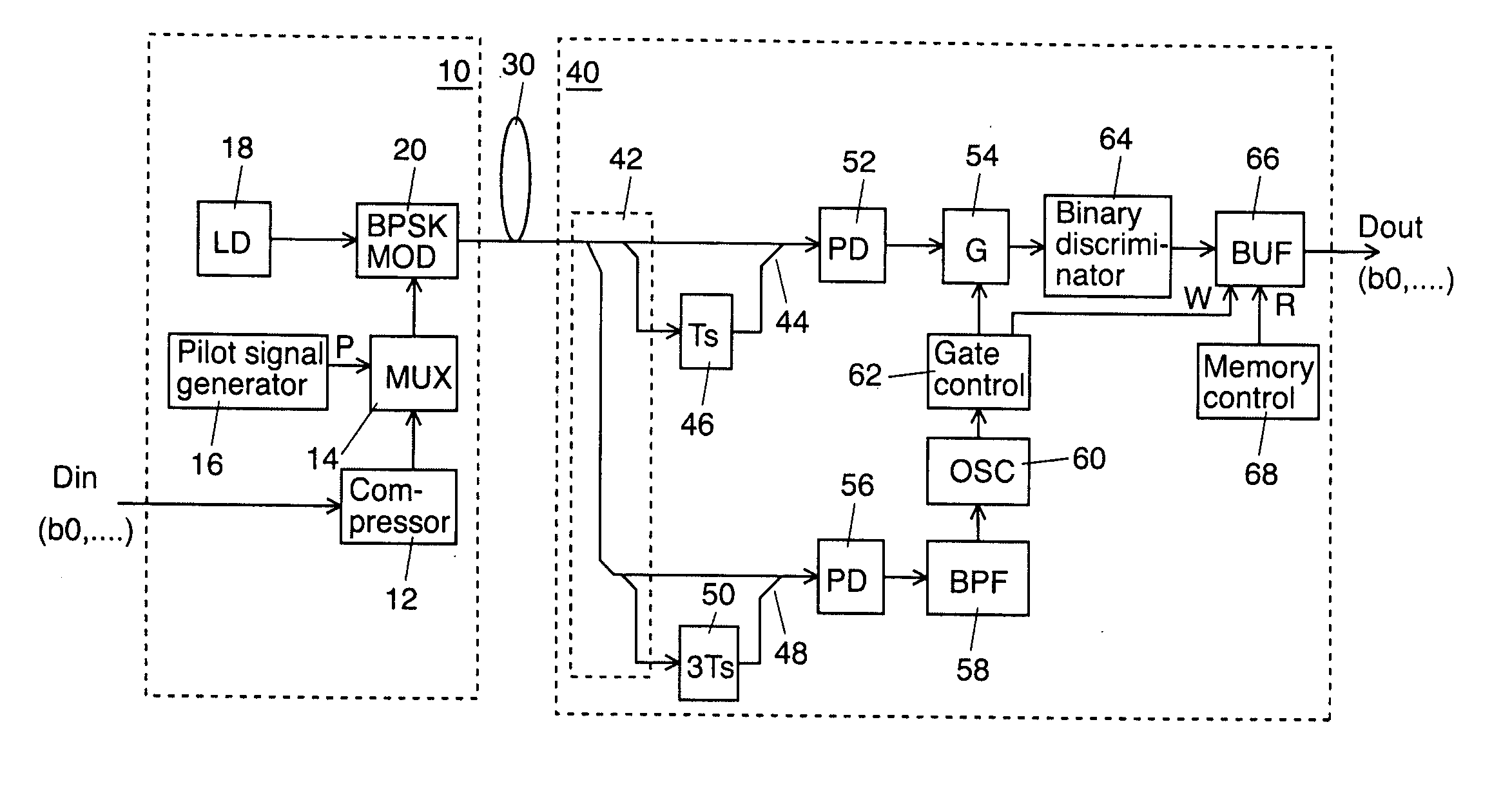
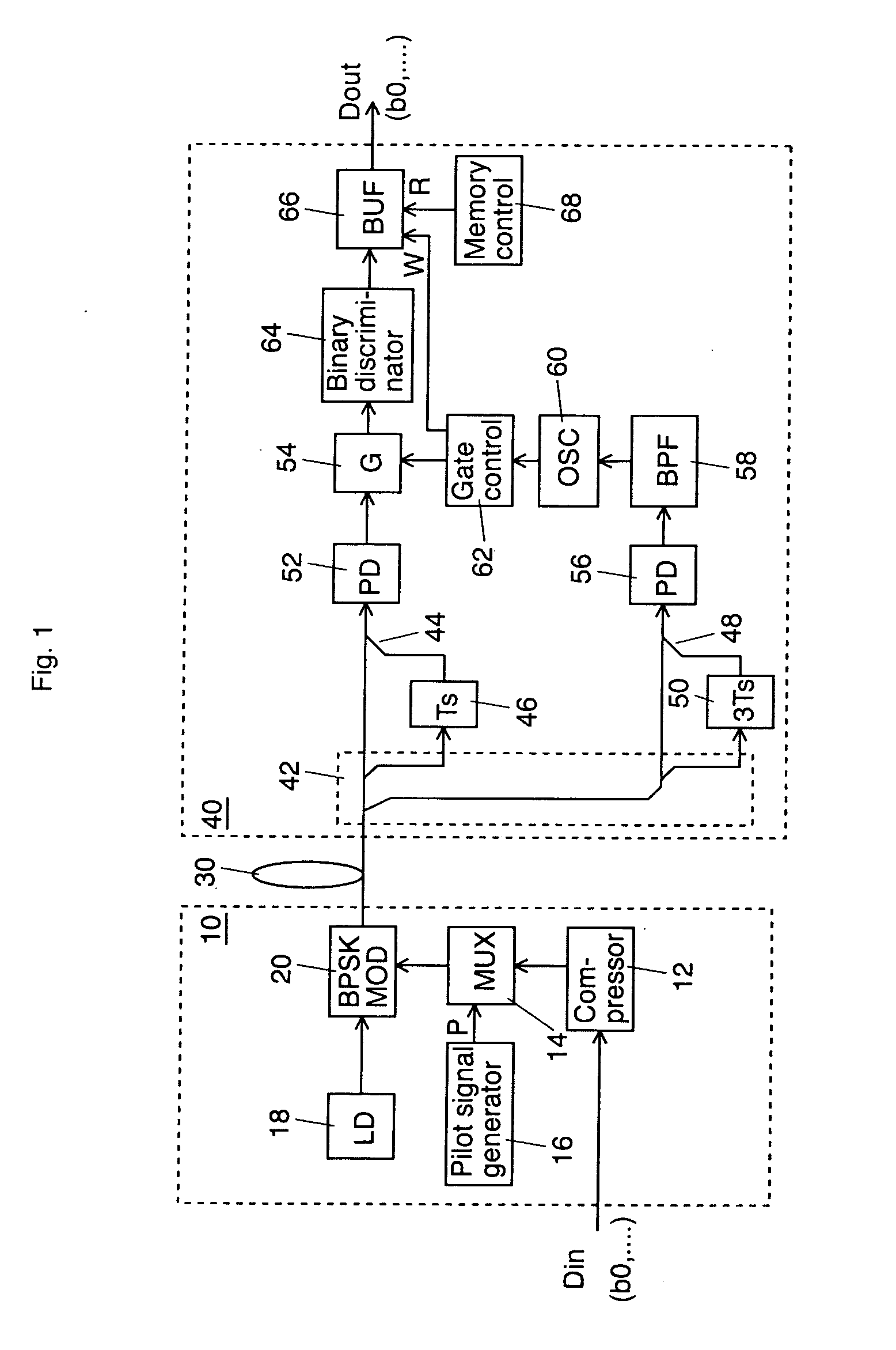
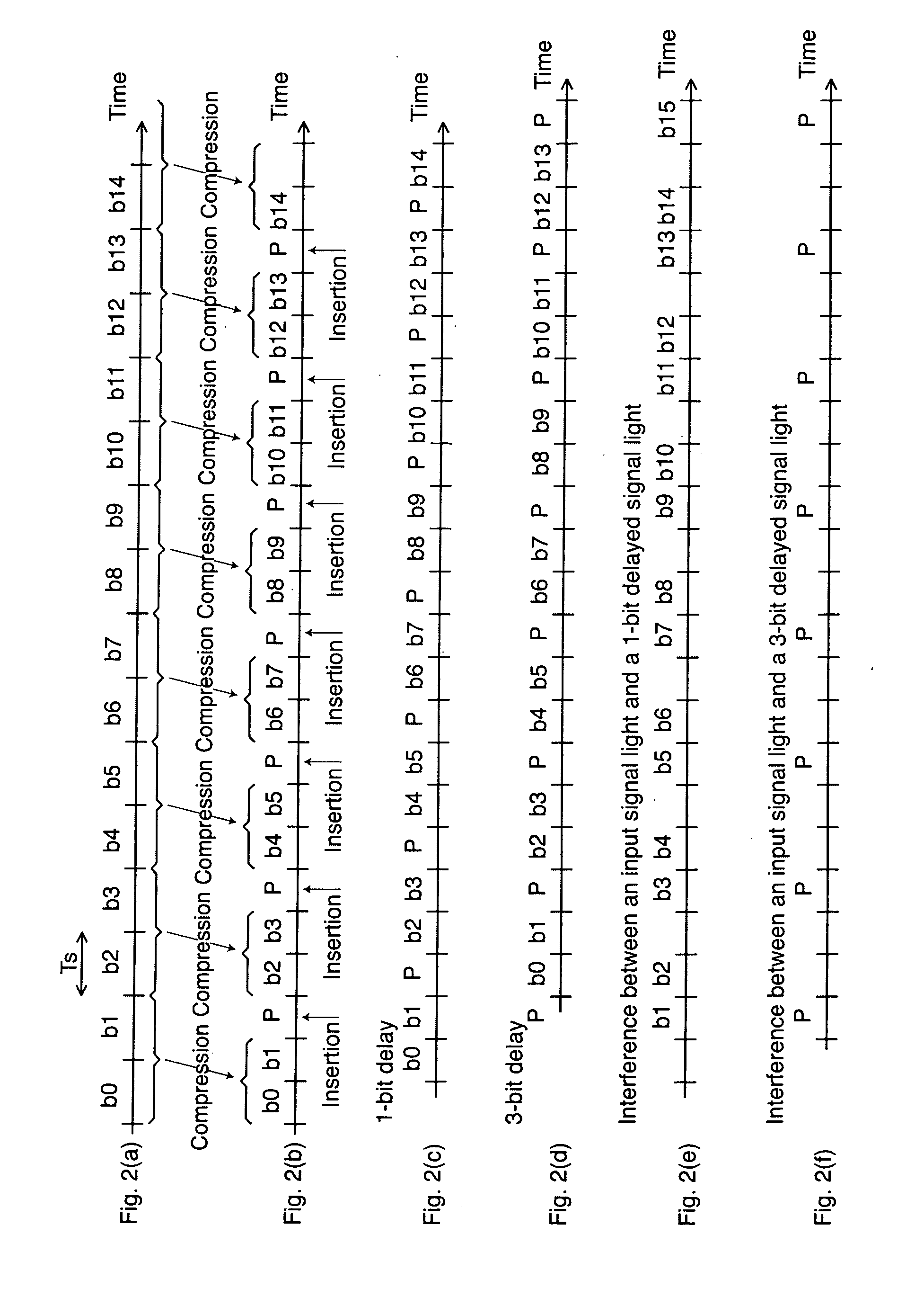
[0024]FIG. 1 shows a schematic block diagram according to a first exemplary embodiment of the invention adapted to an optical transmission system using BPSK (Binary Phase Shift Keying) modulation, and FIG. 2 shows a timing chart of the first embodiment. In the optical stage of this embodiment, a binary digit 0 is expressed as an optical phase 0, a binary digit 1 is expressed as an optical phase π, and a pilot signal being inserted into a signal light or time-division-multiplexed with the signal light is expressed as an optical phase 0.

[0025] A data Din at a bit rate B including a bit string of b0 to b14 as shown in FIG. 2(a) enters an optical transmitter 10. In this embodiment, a pilot signal P is inserted every two bits of the input data Din. For this procedure, a compressor 12 compresses the input data into two third in the time domain. A multiplexer 14 buffers the data c...


PUM


Abstract

An optical transmitter generates a transmission signal having a frame as a unit, the frame including a signal pilot signal with fixed amplitude and phase and two data bits to output the generated signal into a transmission line. In a receiver, a splitter splits the signal light from the transmission line. An optical delay delays the signal light for a 1-bit period. A first combiner combines the signal light from the transmission line and the output signal light from the optical delay. A photodetector converts the combined light into an electrical signal. A 3-bit optical delay, a second combiner, a BPF, and an oscillator generate a frame-timing signal. A gate separates a data from the output from the photodetector under the control of a gate control unit. A binary discriminator binary-discriminates the output signal from the gate.

Description

CROSS REFERENCE TO RELATED APPLICATIONS [0001] This application claims priority to Japanese Patent Application No. 2005-196953, filed on Jul. 6, 2005, the entire contents of which are incorporated herein by reference. FIELD OF THE INVENTION [0002] This invention relates to a data transmission method and its system. BACKGROUND OF THE INVENTION [0003] In high-speed optical transmission, a number of detecting systems are known according to the modulation systems. [0004] A heterodyne detecting system based on a reference carrier is described in “Degradation of Bit-Error Rate in Coherent Optical Communications Due to Spectral Spread of the Transmitter and the Local Oscillator,” IEEE / USA J. Lightwave Technol., Vol. LT-2, pp. 1024-1033, December 1984, by K. Kikuchi, T. Okoshi, M. Nagamatsu, and N. Henmi. This system, similar to the present wireless communication, regenerates a carrier from a received signal to stabilize its frequency using an optical PLL (phase locked loop). This system do...

Claims


Application Information

Patent Timeline
Patent Type & Authority Applications(United States)
IPC IPC(8): H04J14/08H04B10/516H04B10/524H04B10/54H04B10/556H04B10/588H04B10/61H04L27/227
CPCH04B10/505H04B10/5053H04B10/5055H04B10/69H04B10/676H04B10/677H04B10/5561
Inventor KAMIO, YUKIYOSHIMIYAZAKI, TETSUYA
Owner NAT INST OF INFORMATION & COMM TECH
Why Eureka
Try Eureka