Method, apparatus, and computer program product for diagnosing a scan chain failure employing fuses coupled to the scan chain

Inactive Publication Date: 2007-01-11
IBM CORP
View PDF34 Cites 7 Cited by
  • Summary
  • Abstract
  • Description
  • Claims
  • Application Information

AI Technical Summary

Benefits of technology

[0026]FIG. 11 is a representation of the unloaded data of FIG. 10 compared with actual fuse locations to f

Problems solved by technology

A continuing problem for VLSI testing is how to diagnose an exact location of a broken scan chain or chains.
When there is low or zero yield, the scan chains are often broken so that the only opportunity to learn and diagnose the root cause of the problem is defect localization based upon scan chain failure data.
An inability to improve the technology and yield can greatly impact a program or at least severely minimize the revenue that could be realized.
In these low or zero yield situations, the most common failure is often the scan chain.
The LSSD Flush and Scan tests will fail when there is one or more broken scan chains on a device.
Since most other tests utilize the scan chain to perform device tests, diagnostics of the broken scan chain or scan chains with hard DC flush and scan fails is extremely limited.
Also as density of VLSI devices continue to increase, their respective scan chains will continue to increase in size proportionally and thus, this problem will become even more severe.
Fault simulation / test generation, providing extremely vital tools for diagnosing combinational faults, is very inefficient and ineffective for shift register (SR) diagnostics.
Significant drawbacks are that the known solutions require very large data volumes, extremely long simulation times, and are not always 100% reliable, and further not one single known method is always successful all the time.

Method used


Image

  • Method, apparatus, and computer program product for diagnosing a scan chain failure employing fuses coupled to the scan chain
  • Method, apparatus, and computer program product for diagnosing a scan chain failure employing fuses coupled to the scan chain
  • Method, apparatus, and computer program product for diagnosing a scan chain failure employing fuses coupled to the scan chain

Examples


Embodiment Construction

[0027] In accordance with features of the invention, a diagnostics technique is provided which employs fuses coupled to a scan chain to diagnose a defect therein. More particularly, diagnosing of a broken scan chain is accomplished by utilizing, in one embodiment, existing on-chip hardware (such as electronic fuses) to load at multiple locations, for example, a logic value 0 into a broken scan chain which has a stuck-at 1 defect. Scan chain logic values are then unloaded and a determination is made whether the scan chain is defective. If so, then a defect is localized within the scan chain from the unloaded logic values by comparison thereof with the known locations of the latches of the scan chain loaded with the logic value 0 via the fuses. With a minor enhancement to the technique, stuck-at 0 conditions can also be readily diagnosed.

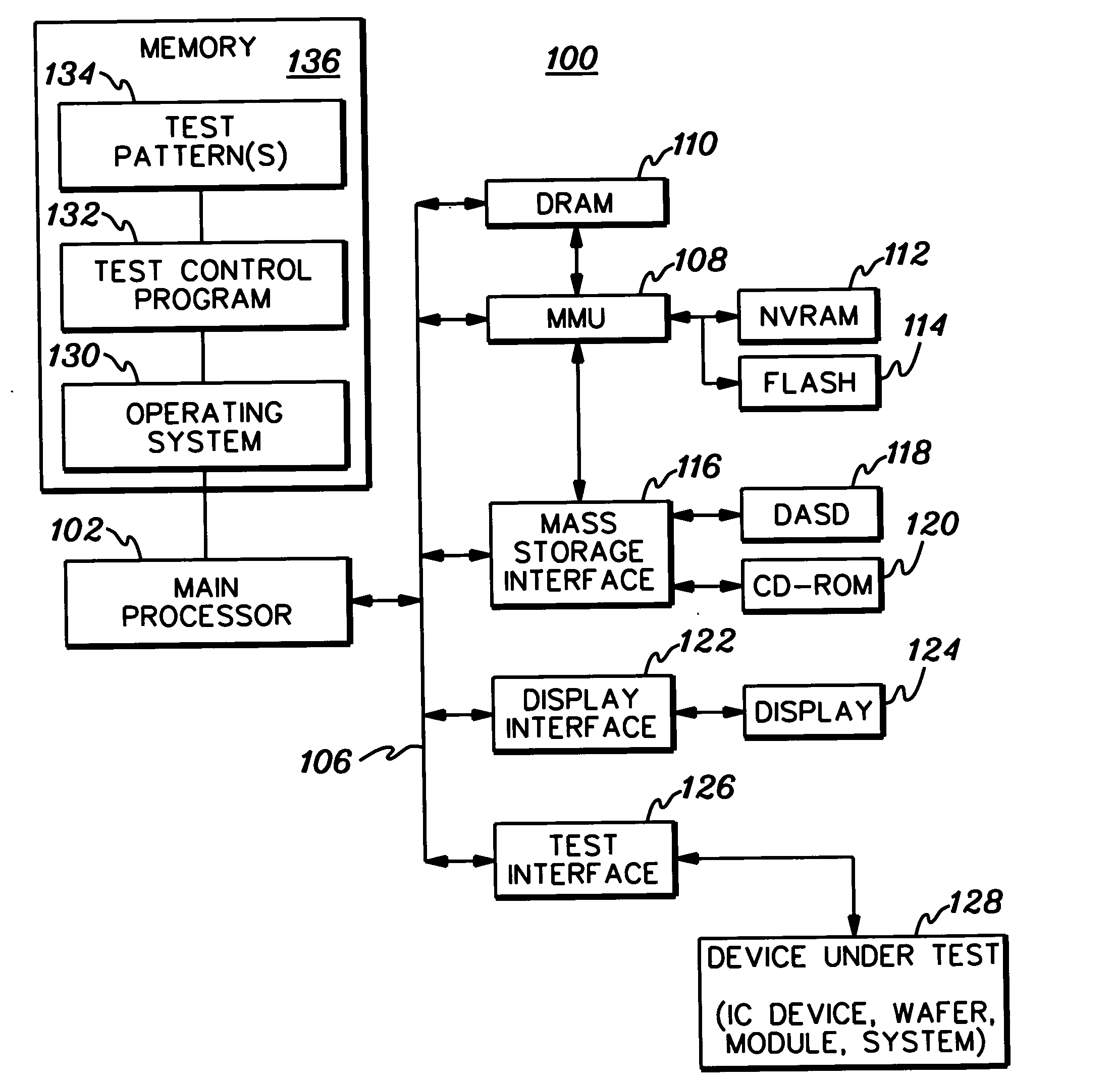
[0028] Referring now to the drawings, in FIG. 1 there is shown an exemplary computer test system generally designated by the reference character 100...


PUM


Abstract

A method, apparatus and computer program product are provided implementing a scan chain diagnostics technique. The diagnostics technique includes employing fuses coupled to latches of the scan chain to load a known logic value into the latches at known locations of the scan chain, and then unloading values from the scan chain, and if the scan chain is defective (for example, based on the unloaded logic values), then localizing a defect in the scan chain from the unloaded logic values by comparison thereof with the known locations of the latches of the scan chain loaded with the known logic value via the fuses. The scan chain may be predesigned with fuses spaced periodically across the chain every n latches to facilitate subsequent localization of a detected defect in the scan chain.

Description

CROSS REFERENCE TO ELATED APPLICATIONS [0001] This application contains subject matter which is related to the subject matter of the following applications, each of which is assigned to the same assignee as this application, and each of which is hereby incorporated herein by reference in its entirety: [0002]“Method, Apparatus, and Computer Program Product For Implementing Deterministic Based Broken Scan Chain Diagnostics”, Anderson et al., U.S. Ser. No. 10 / 821,160, filed Apr. 8, 2004, (IBM Docket No.: ROC920030422US1); [0003]“ABIST-Assisted Detection of Scan Chain Defects”, Burdine et al., U.S. Ser. No. 10 / 728,348, filed Dec. 4, 2003, (IBM Docket No.: ROC920030235US1); and [0004]“Diagnostic Method For Detection of Multiple Defects in a Level Sensitive Scan Design (LSSD)”, Todd M. Burdine, U.S. Ser. No. 10 / 767,046, filed Jan. 29, 2004, (IBM Docket No.: ROC920030281US1). TECHNICAL FIELD OF THE INVENTION [0005] The present invention relates generally to the field of testing and diagnos...

Claims


Application Information

Patent Timeline
IPC IPC(8): G01R31/28
CPCG06F11/2215
Inventor BURDINE, TODD M.FORLENZA, DONATO O.FORLENZA, ORAZIO P.HURLEY, WILLIAM J.TRAN, PHONG T.
Owner IBM CORP
Why Eureka
Try Eureka