Brake control apparatus for vehicle

Inactive Publication Date: 2007-01-25
ADVICS CO LTD
View PDF3 Cites 90 Cited by
  • Summary
  • Abstract
  • Description
  • Claims
  • Application Information

AI Technical Summary

Benefits of technology

[0044] By virtue of this configuration, when the wheels lock during braking, locking of the front wheels always occurs prior to locking of the rear wheels. Accordingly,

Problems solved by technology

However, increasing the regenerative braking force, while placing higher priority on electrical energy collection efficiency than on the front-wheel braking force distribution, means that the driven wheels become more likely to lock.
Incidentally, c

Method used


Image

  • Brake control apparatus for vehicle
  • Brake control apparatus for vehicle
  • Brake control apparatus for vehicle

Examples


Embodiment Construction

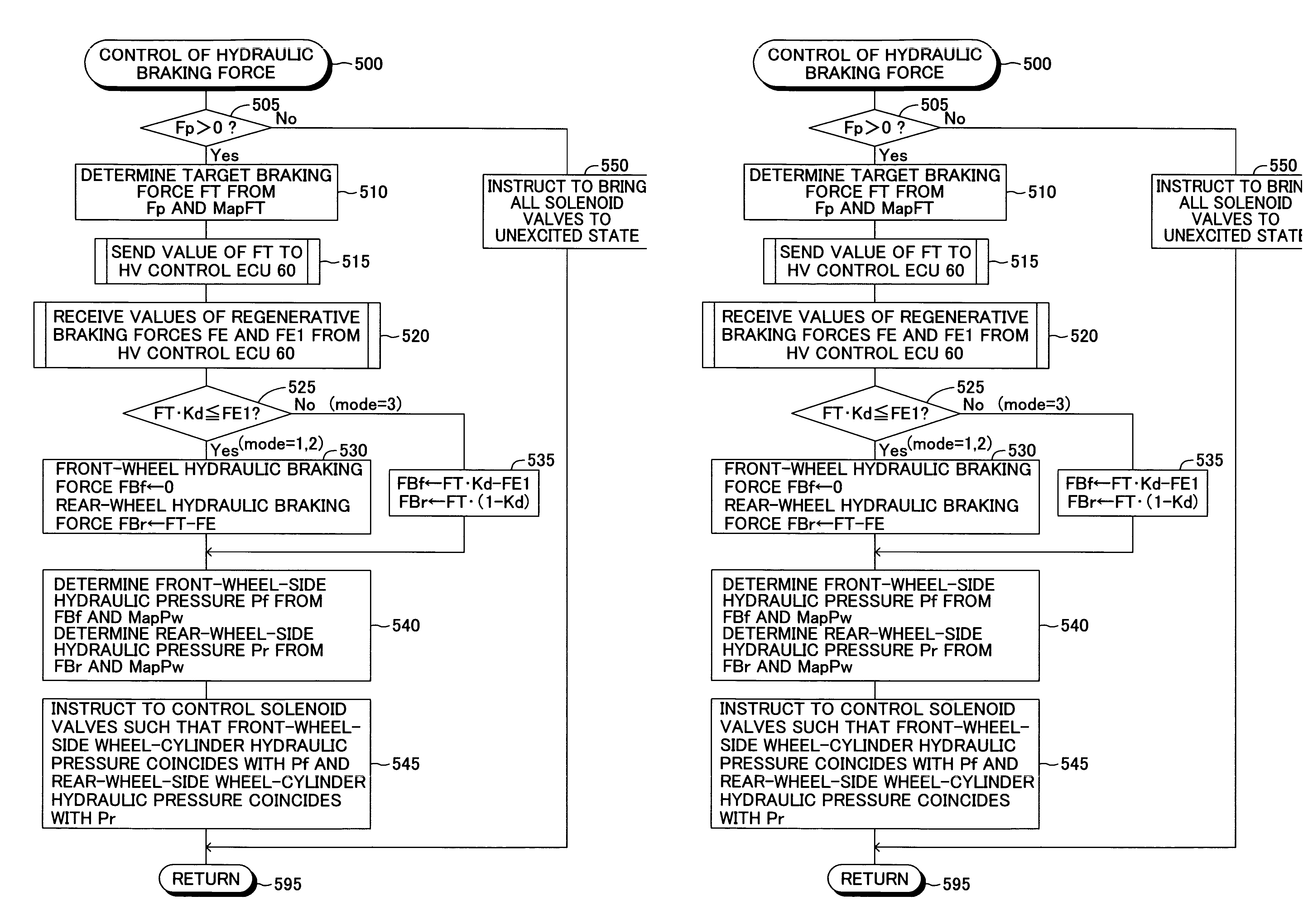
[0056] A brake apparatus (brake control apparatus) for a vehicle according to an embodiment of the present invention will be described with reference to the drawings.

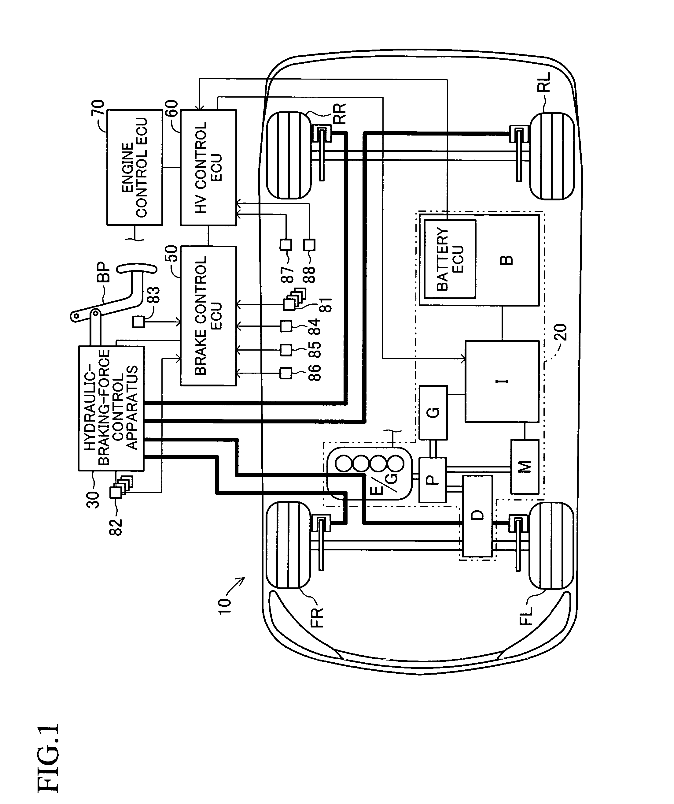
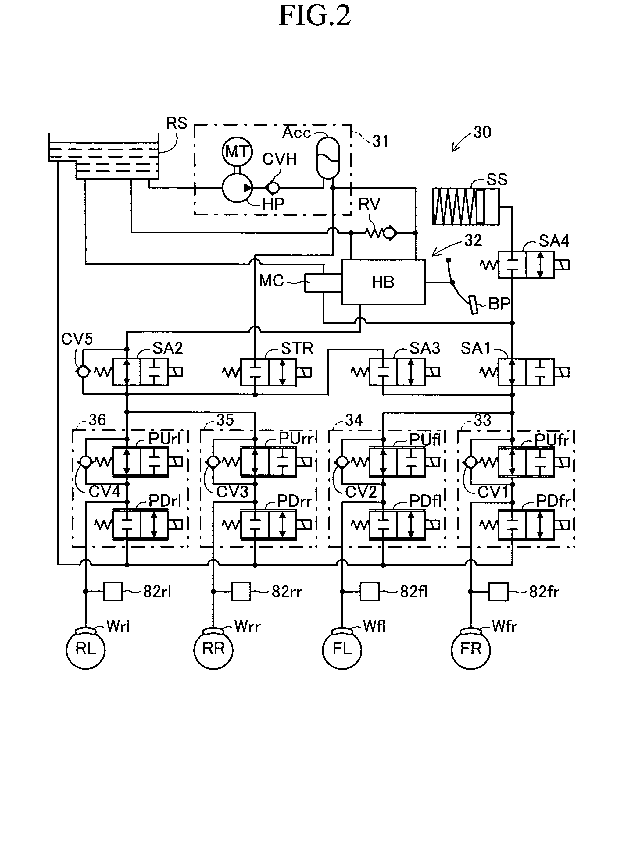
[0057]FIG. 1 schematically shows the structure of a vehicle equipped with a brake apparatus 10 according to the embodiment of the present invention. The illustrated vehicle is a so-called hybrid vehicle of a front-wheel drive type which uses an engine and a motor as a drive source for driving the front wheels and which includes two brake hydraulic circuits (that is, front-rear piping system); i.e., a system for the two front wheels and a system for the two rear wheels.

[0058] This brake apparatus 10 includes a hybrid system 20 having two types of power sources; i.e., an engine E / G and a motor M; a hydraulic-braking-force control apparatus 30 which controls hydraulic braking forces (specifically, wheel-cylinder hydraulic pressures) acting on the wheels; a brake control ECU 50; a hybrid control ECU (hereinafter called “H...


PUM


Abstract

A brake apparatus for a vehicle generally sets an upper limit value of regenerative braking force to the maximum value of the regenerative braking force which can be generated at the present. In the case of a front-wheel-drive vehicle, the total braking force, the sum of front-wheel braking force (front-wheel hydraulic braking force+regenerative braking force) and rear-wheel braking force (rear-wheel hydraulic braking force), is rendered coincident with a target braking force corresponding to a brake pedal depressing force, and the regenerative braking force is set to a largest possible value equal to or less than the upper limit value. As a result, the regenerative braking force can be larger than front-wheel-side target distribution braking force. The upper limit value is decreased from the maximum value by an amount corresponding to the degree of easiness of occurrence of a locking tendency at the driven wheels (front wheels).

Description

BACKGROUND OF THE INVENTION [0001] 1. Field of the Invention [0002] The present invention relates to a brake control apparatus for a vehicle. [0003] 2. Description of the Related Art [0004] Recently, there has been developed a brake control technique which is applied to a motor-driven vehicle using a motor as a power source for driving driven wheels or to a so-called hybrid vehicle using a motor and an internal combustion engine and which performs regeneration-coordinative brake control using braking force on the basis of hydraulic pressure (hydraulic braking force; frictional braking force) as well as regenerative braking force generated by the motor. [0005] A brake apparatus for a vehicle which performs the above-described regeneration-coordinative brake control is generally designed to adjust the regenerative braking force and the hydraulic braking force in such a manner that the total braking force (entire braking force acting on the vehicle), which is the sum of regenerative br...

Claims


Application Information

Patent Timeline
IPC IPC(8): B60T8/60
CPCB60K6/445Y02T10/6239B60L7/14B60L7/26B60L11/123B60L11/14B60L2210/20B60L2220/14B60L2250/26B60T8/267B60T8/4081B60W10/06B60W10/08B60W10/184B60W20/00B60W30/18127B60W2720/403Y02T10/6217Y02T10/6286Y02T10/7077Y02T10/725Y02T10/92B60L3/102B60W2540/12B60L50/16B60L50/61Y02T10/62Y02T10/70Y02T10/7072Y02T10/72B60W2710/18
Inventor KOKUBO, KOICHIMATSUURA, MASAHIROSAITO, SHIGERUSENGOKU, YUJI
Owner ADVICS CO LTD
Why Eureka
Try Eureka