Air filter sensor

a technology of air filter and sensor, which is applied in the direction of mechanical time indication, dispersed particle filtration, combination devices, etc., can solve the problems of reduced air flow rate, increased back pressure, increased work that must be performed and energy consumed by the blower or fan unit,

Inactive Publication Date: 2007-02-01
FALCON MICHAEL D
View PDF22 Cites 5 Cited by
  • Summary
  • Abstract
  • Description
  • Claims
  • Application Information

AI Technical Summary

Benefits of technology

[0009] The present invention is directed towards a sensor including, inter alia, a body having first and second spaced-apart apertures, the first aperture having a shape producing an audible noise upon a fluid passing therethrough; a piston positioned within the body; and a chamber having an additional fluid disposed therein, with a volume of the additional fluid placing the piston between first and second positions, the first position impeding the first volume of fluid and the second position allowing the first volume of fluid to pass through the first aperture. These and other embodiments are described more fully below.

Problems solved by technology

This reduced air flow rate reduces the efficiency of the heating or cooling system and the effective heating or cooling of the dwelling or commercial establishment.
The partially clogged filter also causes increased back pressure to be applied to the blower or fan which generates the air flow and this back pressure increases the work that must be performed and the energy consumed by the blower or fan unit.
The resulting increased load increases the wear rate of the moving parts in the heating or cooling system and also results in increased operating costs.
This is time consuming and can often result in dirty filters not being changed on time due to the failure to remember to check the filter.
However, the replacement of air filters may be a function of time.

Method used


Image

  • Air filter sensor
  • Air filter sensor
  • Air filter sensor

Examples


first embodiment

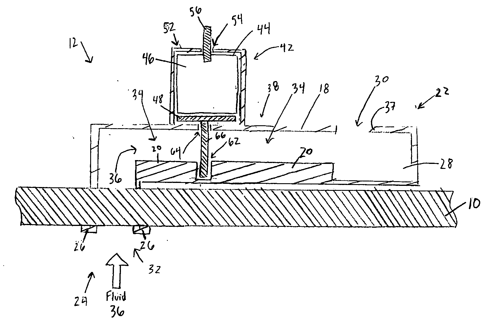
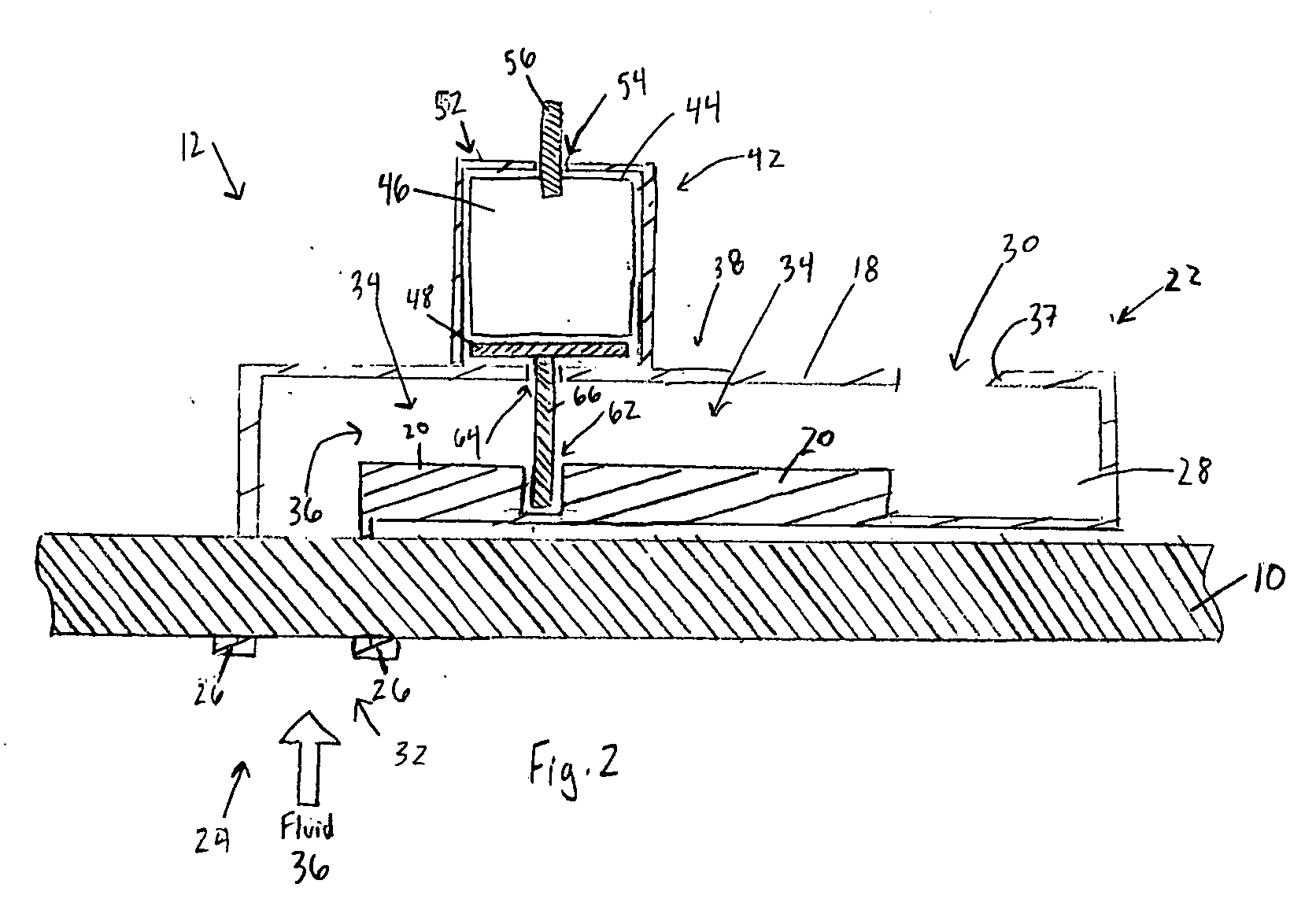
[0023] Referring to FIG. 2, in a first embodiment, sensor 12 comprises a body 18 having a section 20 and spaced-apart first and second ends 22 and 24. In a further embodiment, section 20 may comprise a cavity (not shown) positioned therein. Second end 24 may comprise a protrusion 26. Protrusion 26 facilitates coupling sensor 12 to air filter 10 and more specifically, coupling sensor 12 to filter material 16, shown in FIG. 1. In a further embodiment, second end 24 may comprise a plurality of protrusions 26. In a further embodiment, second end 24 may comprise any coupling element to couple sensor 12 to air filter 10, with such coupling elements including, but is not limited to, pins, barbs, clips, clamps, tape, and adhesives. First end 22 comprises a cavity 28. As shown, cavity 28 comprises a rectangular geometrical shape, however cavity 28 may comprise any desired geometrical shape.

[0024] Sensor 12 further comprises apertures 30 and 32 having a pathway 34 extending therebetween. Aper...

second embodiment

[0033] Referring to FIG. 8, in a second embodiment, piston 66 may be positioned adjacent to first end 22 of body 18. As a result, when piston 66 is placed in the first position, piston 66 may substantially be in superimposition with aperture 30, and thus, impede a flow of fluid 36 thru pathway 34.

[0034] Referring to FIG. 9, analogously to the above-mentioned, piston 66 may be placed in the second position as a result of a decreasing volume of fluid 46, and thus, expose aperture 30. Fluid 36 may then flow through pathway 34 to exit through aperture 30 and produce the audible noise, analogous to the above-mentioned.

[0035] Referring to FIG. 10, in a further embodiment, cavity 28 may comprise a fluid 68. Fluid 68 may have an evaporation rate associated therewith. The evaporation rate of fluid 68 may depend upon, inter alia, a composition of fluid 68. Fluid 68 may comprise such compositions as those mentioned-above with respect to fluid 46, shown in FIG. 2. Cavity 28 may further compris...


PUM

PropertyMeasurementUnit
shapeaaaaaaaaaa
volumeaaaaaaaaaa
forceaaaaaaaaaa

Abstract

The present invention is directed towards a sensor including, inter alia, a body having first and second spaced-apart apertures, the first aperture having a shape producing an audible noise upon a fluid passing therethrough; a piston positioned within the body; and a chamber having an additional fluid disposed therein, with a volume of the additional fluid placing the piston between first and second positions, the first position impeding the first volume of fluid and the second position allowing the first volume of fluid to pass through the first aperture.

Description

BACKGROUND OF THE INVENTION [0001] The present invention is directed towards an audible sensor. More specifically, the present invention is directed towards a sensor for an air filter to indicate a replacement thereof. [0002] Heating and cooling systems for houses and other dwellings and for at least some commercial establishments include a system for transmitting heated or cooled air throughout the dwelling or commercial establishment. These systems for transmitting heated or cooled air also include filtration equipment for removing particulate matter from the heated or cooled air and this filtration equipment, particularly for dwellings, normally includes one or more mechanical filters formed from fibrous materials. [0003] These filter materials serve the function of mechanically blocking particulate matter that is in the air flowing in circuitous paths through the filter material. The particulate matter becomes attached to individual fibers and, over a period of time, progressive...

Claims


Application Information

Patent Timeline
Patent Type & Authority Applications(United States)
IPC IPC(8): B01D46/00
CPCB01D46/008F24F2011/0093F24F11/0086B01D46/0086F24F11/30F24F11/39B01D46/88F24F11/526
Inventor FALCON, MICHAEL D.
Owner FALCON MICHAEL D
Why Eureka
Try Eureka