Filtration media for filtering particulate material from gas streams

a technology of filtration media and gas stream, which is applied in the direction of gravity filters, filtration separation, and separation processes, can solve the problems of inability to meet the requirements of filtration media, inability to achieve the stability of hepa filters used in these applications, and inability to achieve the stability of filtration media performan

Active Publication Date: 2007-06-26
DUPONT SAFETY & CONSTR INC
View PDF26 Cites 91 Cited by
  • Summary
  • Abstract
  • Description
  • Claims
  • Application Information

AI Technical Summary

Problems solved by technology

In such applications, particulate material in the air is occasionally responsible for product defects or loss of containment of substances within the cleanroom.
Instability of performance of the HEPA filters used in these applications is not acceptable.
Each of these classes of filtration media has its limitations.
Microglass fibers and blends containing microglass fibers have the limitation that they are typically relatively brittle when pleated, and produce undesirable yield losses as HEPA filters are required to be 100% inspected.
Spot repairs are a tedious manual process.
Such filters suffer a few limitations.
First, being based on the electrical charge for effective capture of particulates, the performances of such filters are greatly influenced by air humidity, causing charge dissipation.
These publications do not disclose high efficiency particulate air filter media or a process for achieving high efficiency air filtration.

Method used


Image

  • Filtration media for filtering particulate material from gas streams

Examples


examples 1-4

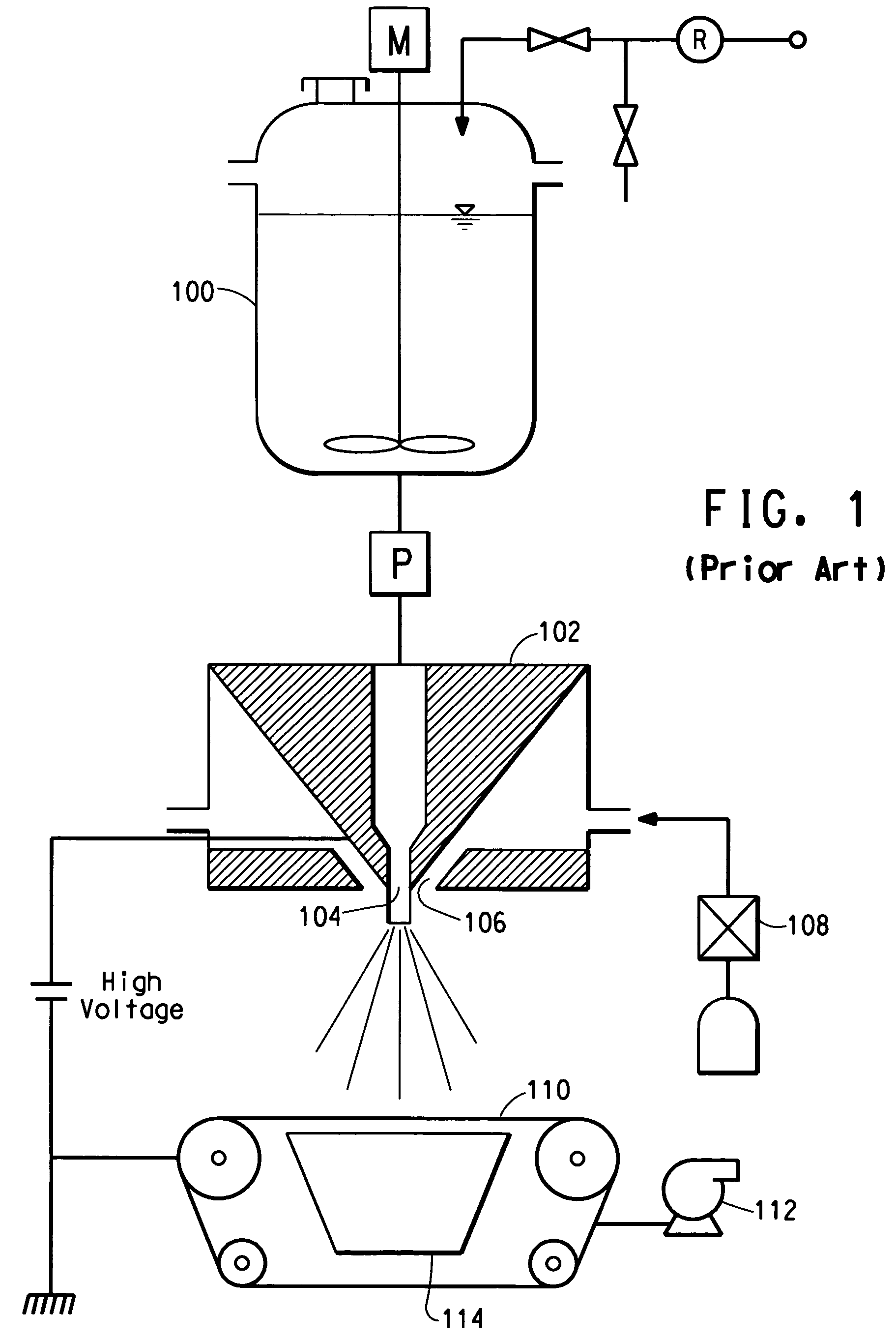
[0037]Nanofiber layers were made by electroblowing a solution of DuPont Nylon 66-FE 3218 polymer having a density of 1.14 g / cc (available from E. I. du Pont de Nemours and Company, Wilmington, Del.) at 24 weight percent in formic acid at 99% purity (available from Kemira Oyj, Helsinki, Finland). The polymer and solvent were fed into a solution mix tank, the solution transferred into a reservoir and metered through a gear pump to an electroblowing spin pack having spinning nozzles, as described in PCT Patent Publication No. WO 03 / 080905. The spin pack was 0.75 meter wide and had 76 spinning nozzles. The pack was at room temperature with the pressure of the solution in the spinning nozzles at 10 bar. The spinneret was electrically insulated and applied with a voltage of 75 kV. Compressed air at a temperature of 44° C. was injected through air nozzles into the spin pack at a rate of 7.5 m3 / minute and a pressure of 660 mm H2O. The throughput of the solution was 2 cc / hole / mm. The fibers ...

example 2

[0040]The above described process was followed. The porous collection belt was moving at 11-3 m / minute. The vacuum chamber pulled a vacuum of 140 mm H2O beneath the porous belt.

[0041]A 60 m long sample was made by making two layers of continuous nanofibers having a nominal 10.0 g / m2 basis weight each, then one layer of nanofibers having a nominal basis weight of 5.0 g / m2, resulting in a total measured basis weight as set forth in Table 1. The fibers in the web formed had an average diameter of about 375 nm. The filtration efficiency was tested at various particle size challenges, and the results are given in Table 2. Pressure Drop (mm of water) was also measured and the results are given in Table 3.

example 3

[0042]The above described process was followed. The porous collection belt was moving at 11.3 m / minute. The vacuum chamber pulled a vacuum of 160 mm Hg beneath the porous belt.

[0043]A 60 m long sample was made by making two layers of continuous nanofibers having a nominal 10.0 g / m2 basis weight each, then two layers of nanofibers having a nominal basis weight of 5.0 g / m2 each, resulting in a total measured basis weight as set forth in Table 1. The fibers in the web formed had an average diameter of about 368 nm. The filtration efficiency was tested at various particle size challenges, and the results are given in Table 2. Pressure Drop (mm of water) was also measured and the results are given in Table 3.


PUM

PropertyMeasurementUnit
thicknessaaaaaaaaaa
diameteraaaaaaaaaa
face velocityaaaaaaaaaa

Abstract

Filtration media are disclosed for use in high efficiency air filters for filtering particulate matter in air. The media make use of at least one layer of fibers having a diameter less than 1000 nanometers sandwiched between two scrim layers to achieve high efficiency particulate air (HEPA) filtration performance at relatively low pressure drops.

Description

BACKGROUND OF THE INVENTION[0001]The present invention relates to filtration media for use in high efficiency air filters, for filtering particulate material from gas streams.[0002]High efficiency particulate air (HEPA) level performance is critical to many of the processes in which HEPA filtration is used, such as semiconductor manufacturing and bio cleanrooms. In such applications, particulate material in the air is occasionally responsible for product defects or loss of containment of substances within the cleanroom. Instability of performance of the HEPA filters used in these applications is not acceptable.[0003]Nonwoven filter elements can be used as surface loading media in HEPA filtration. The media are generally constructed to be permeable to gas flow, and to also have a sufficiently fine pore size and appropriate porosity to inhibit the passage of particles greater than a selected size therethrough. As particulate materials pass through the filter, the upstream side of the ...

Claims


Application Information

Patent Timeline
Patent Type & Authority Patents(United States)
IPC IPC(8): B01D46/00
CPCB01D39/1623B01D39/16B01D46/00
Inventor BRYNER, MICHAEL ALLENHOVANEC, JOSEPH BRIANJONES, DAVID C.LIM, HYUN SUNGWISEMAN, B. LYNNE
Owner DUPONT SAFETY & CONSTR INC
Why Eureka
Try Eureka