Gas turbine power generation system

a technology of power generation system and gas turbine, which is applied in the direction of machine/engine, machine support, combustion air/fuel air treatment, etc., can solve the problems of increasing the dedicated space required for installation, further aggravating inconvenience, and troublesome air filter replacement work, so as to facilitate air filter replacement and reduce the dedicated installation space

Inactive Publication Date: 2005-11-08
HONDA MOTOR CO LTD
View PDF5 Cites 99 Cited by
  • Summary
  • Abstract
  • Description
  • Claims
  • Application Information

AI Technical Summary

Benefits of technology

[0014]An object of this invention is therefore to overcome the foregoing problems by providing a gas turbine power generation system wherein the lay

Problems solved by technology

This is inconvenient because it requires open spaces to be left on two sides and therefore increases the total dedicated space required for the installation.
The work of changing the air filter is therefore more troublesome.
This further aggravates the inconvenience of having to dedicate a large space for the installation.
In addition, the gas turbine power generator has a number of noise sources that produce, for instance, air intake noise, exhaust noise, and engine rotation noise.
While noise can be reduced by using large amounts of sound-absorbing material and by lengthening the duct of the air intake system and installing an interposed silencer, these m

Method used


Image

  • Gas turbine power generation system
  • Gas turbine power generation system
  • Gas turbine power generation system

Examples


Embodiment Construction

[0038]A gas turbine power generation system according to an embodiment of the present invention will now be explained with reference to the attached drawings.

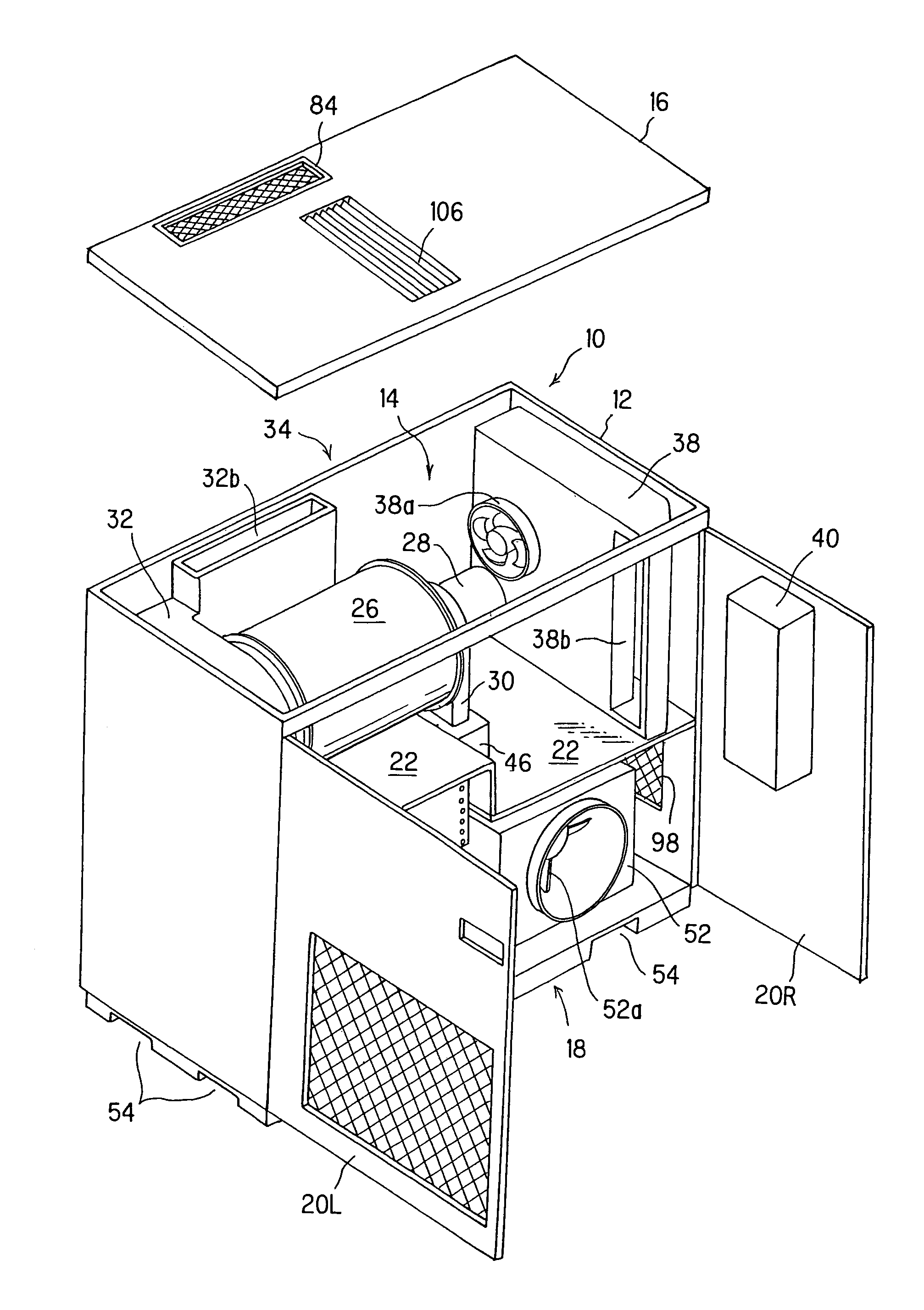
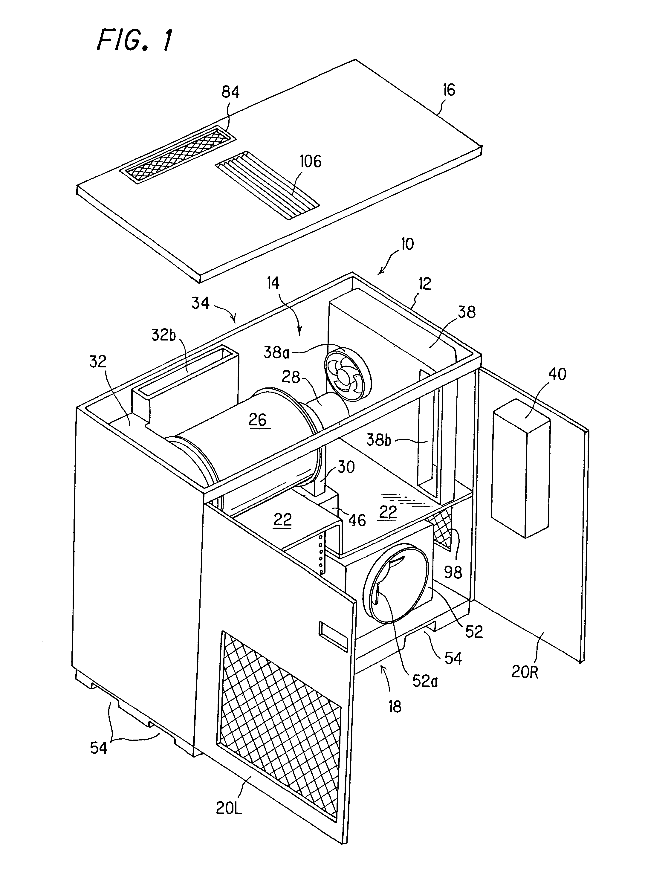
[0039]FIG. 1 is a perspective view showing the gas turbine power generation system as a whole.

[0040]In FIG. 1, the gas turbine power generation system (hereinafter sometimes referred to simply as “generator system”) is denoted by reference numeral 10. The generator system 10 is equipped with a substantially box-like housing 12. The top of the housing 12 is formed as an openable and closable upper face for use in maintenance (hereinafter called “first openable maintenance face 14”). The first openable maintenance face (opening) 14 can be opened / closed by removing / attaching a roof (cover) 16.

[0041]Another of the faces of the housing 12 is also formed to be openable for maintenance and is designated a second openable maintenance face (opening) 18. The face formed with the second openable maintenance face 18 is at the front of the ...


PUM


Abstract

In a gas turbine power generation system having a gas turbine engine and a generator connected to the engine, maintenance ease is enhanced by forming the housing to have openable maintenance faces at two of its faces. Installation space is reduced and a compact configuration is achieved by providing a partition that divides the interior space of the housing into two regions into an upper bay and a lower bay, mounting the engine in the upper bay and mounting air intake duct in the lower bay at a location directly under the engine. Noise is reduced by using a partition to define two separate spaces (bays) and mounting the engine and the air intake duct in the upper and lower bays. Noise is also reduced by preventing engine rotation noise from escaping to the outside through the air intake duct. Moreover, it achieves a reduction in the amount of dedicated space required by constituting the air intake duct of a duct section having an air inlet at a plane coincident with that of the maintenance opening and a filter-housing section for removably housing an air filter, thereby enabling a common space to be utilized for that required in front of the maintenance opening and the air inlet.

Description

BACKGROUND OF THE INVENTION[0001]1. Field of the Invention[0002]This invention relates to a gas turbine power generation system, particularly to a gas turbine power generation system that uses a generator power source comprising a single-spool micro gas turbine engine whose compressor and turbine are coaxially aligned.[0003]2. Description of the Related Art[0004]The term “micro gas turbine” or “micro turbine” is commonly used to refer to a gas turbine power generation system whose generator is driven by a single-spool gas turbine engine including a coaxially aligned compressor and turbine. In recent years, the micro gas turbine has attracted attention for its utility as an electric power generation means for multifamily housing units, high-rise apartment buildings, factories, large retail stores, leisure facilities, schools, hospitals and the like.[0005]In this type of gas turbine power generator, the engine is supplied with air through an air intake stage including a filter and duc...

Claims


Application Information

Patent Timeline
IPC IPC(8): F01D25/24F02C7/055F02C7/04F02C7/20F02C7/042H02K41/03
CPCF01D25/24F02C7/04F02C7/042F02C7/055F02C7/20H02K41/03H02K2201/15H02K2201/18F05D2220/76
Inventor KUROKAWA, MASATOSHIKOBAYASHI, NOBUYUKIYOSHINO, TSUTOMU
Owner HONDA MOTOR CO LTD
Why Eureka
Try Eureka