Gas turbine on-line compressor water wash system

a compressor and water wash technology, applied in the direction of machines/engines, liquid fuel engines, machine/engines, etc., can solve the problems of affecting the operation of the compressor, and not addressing the specific travel path of mist droplets,

Inactive Publication Date: 2007-02-08
GENERAL ELECTRIC CO
View PDF9 Cites 39 Cited by
  • Summary
  • Abstract
  • Description
  • Claims
  • Application Information

AI Technical Summary

Benefits of technology

[0009] The present application further describes an on-line water wash system for a compressor having a bellmouth casing with a region of known high velocity inlet airflow, a number of rotating blades, and a number of struts. The water wash system may include a number of water nozzles positioned with...

Problems solved by technology

This known system, however, does not address the specific travel path of the mist droplets.
As a result of this, erosion of the first stage rotating blade may occur at undesirable locations along the leading...

Method used


Image

  • Gas turbine on-line compressor water wash system
  • Gas turbine on-line compressor water wash system
  • Gas turbine on-line compressor water wash system

Examples


Embodiment Construction

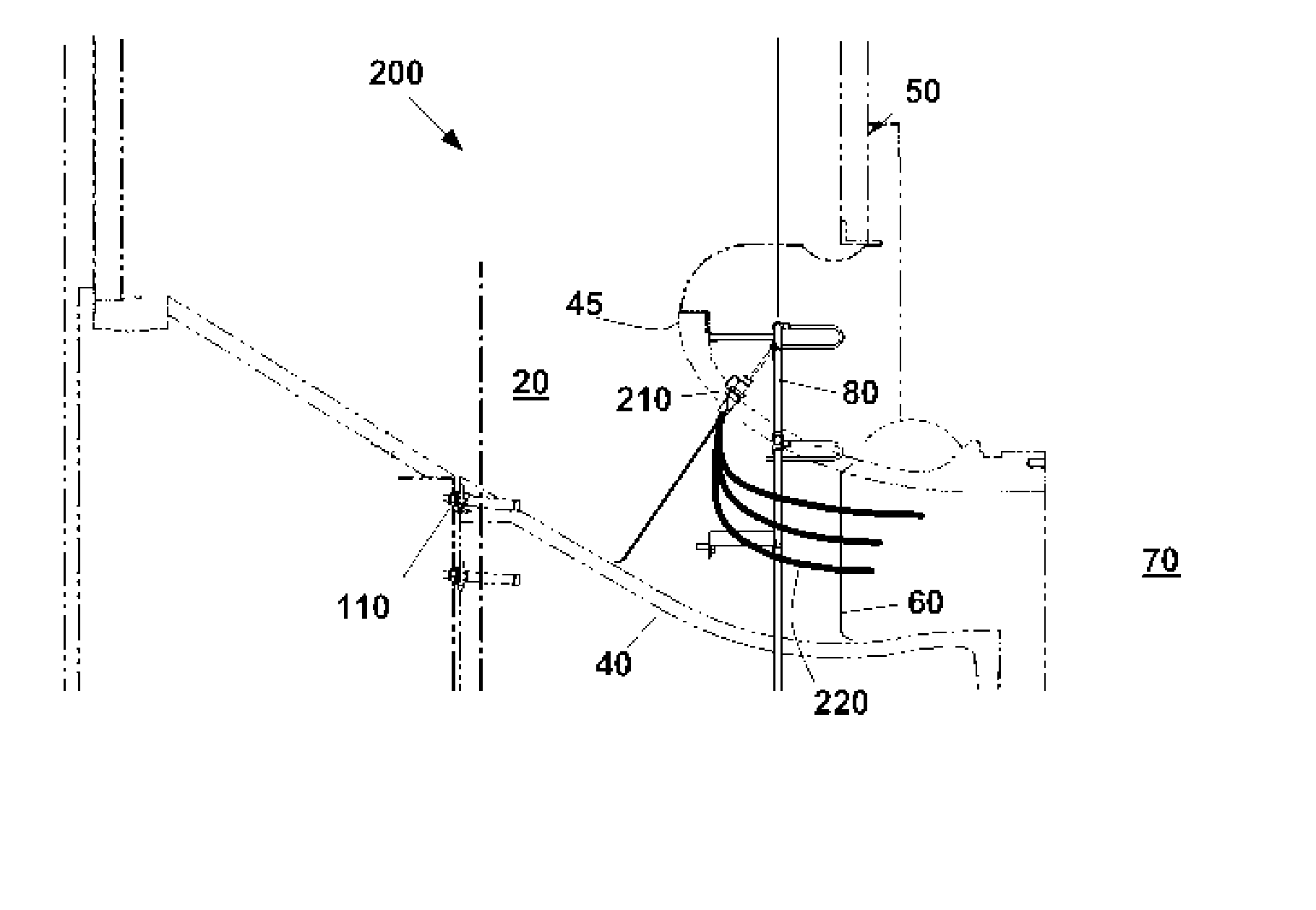
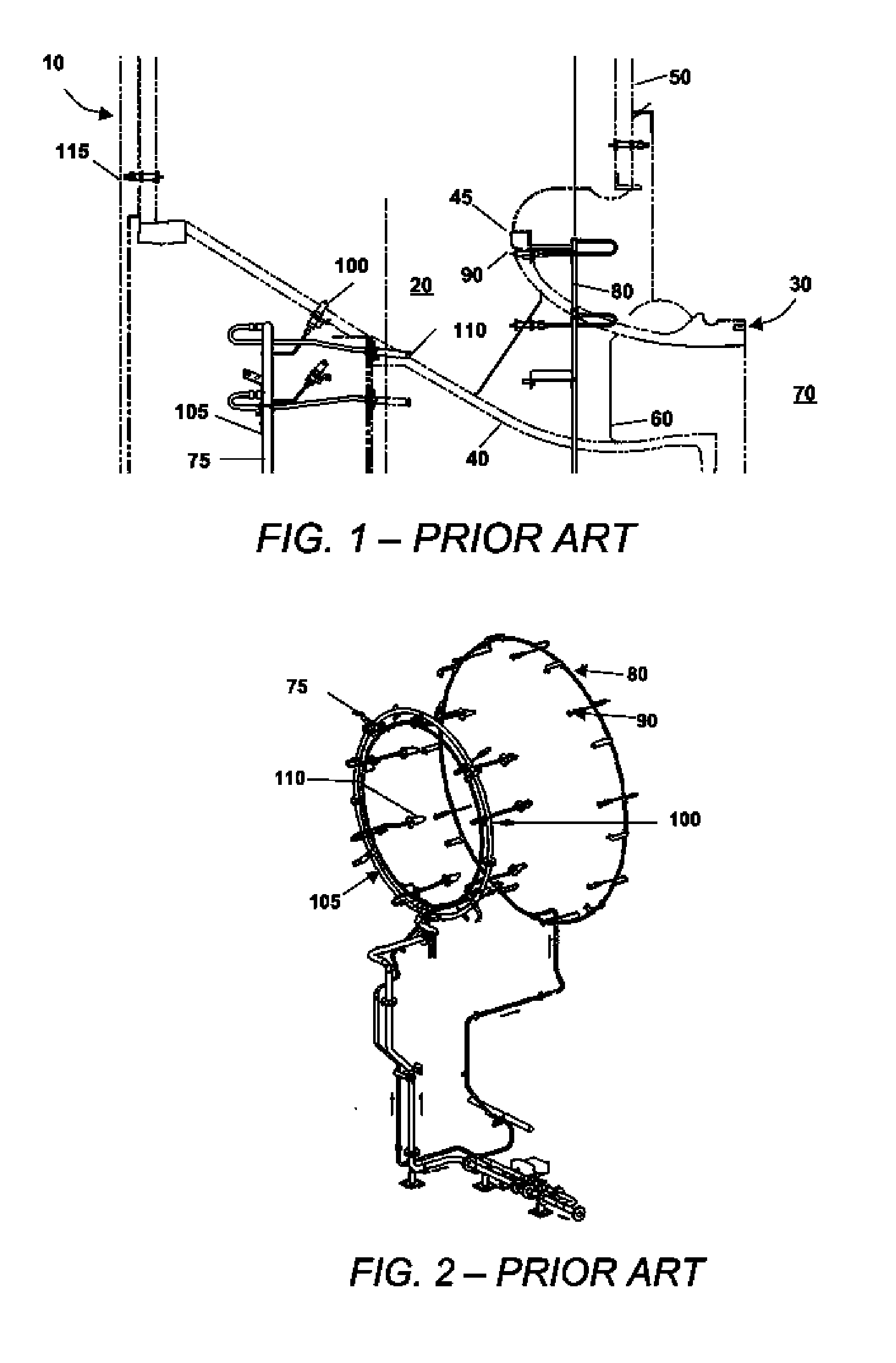
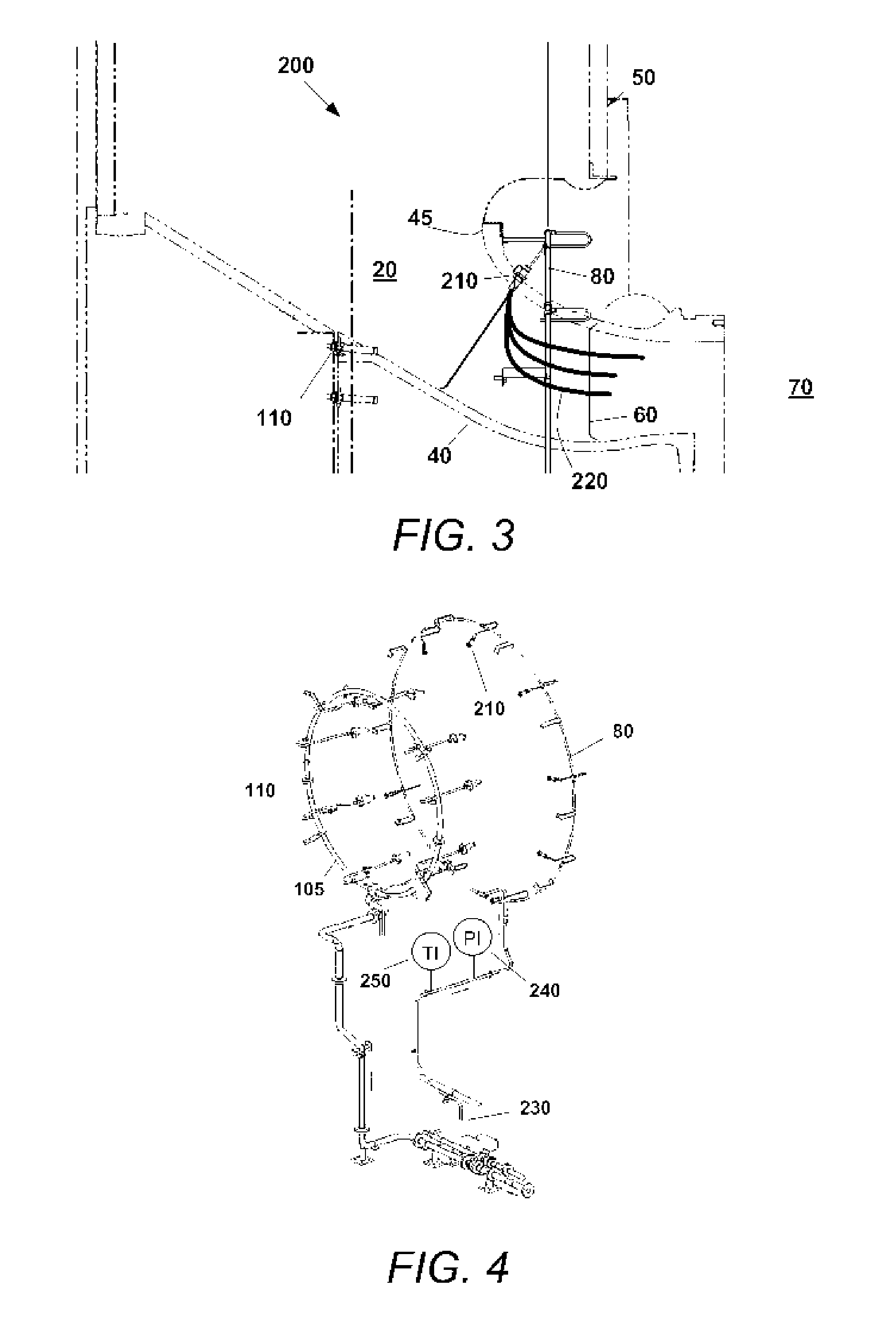
[0015] Referring now to the drawings, in which like numerals refer to like elements throughout the several views, FIGS. 1 and 2 show an example of a known water wash system 10. The nozzles of the water wash system 10 are positioned about an air inlet pathway 20 of a compressor 30. Generally described, the air inlet pathway 20 of the compressor 30 is defined by a bellmouth casing 40 in communication with an inlet plenum 50. The bellmouth casing 40 includes an inlet 45 adjacent to the inlet plenum 50. The air inlet pathway 20 then leads past a number of bellmouth struts 60 and into a number of rotating blades 70 of the compressor 30.

[0016] As shown in FIG. 2, the on-line water wash system 10 includes a number of independent supply manifolds, a forward manifold 75 and an aft manifold 80. Each manifold supplies water to a number of corresponding nozzles, a number of aft nozzles 90 and a number of forward nozzles 100. This arrangement is similar to that shown in U.S. Pat. No. 5,011,540 ...


PUM


Abstract

An on-line water wash system for a compressor having a bellmouth casing with a region of known high velocity inlet airflow and a number of rotating blades. The water wash system may include a number of water nozzles positioned within the bellmouth casing about the region of known high velocity inlet airflow and a stream of water droplets. The stream of water droplets is targeted by the water nozzles so as to avoid the bellmouth casing and the rotating blades.

Description

TECHNICAL FIELD [0001] The present application relates generally to gas turbines engines and more particularly relates to an improved on-line compressor water wash system for gas turbine engines. BACKGROUND OF THE INVENTION [0002] An on-line water wash system is commonly used to remove contaminants from gas turbine compressors. The on-line system recovers gas turbine efficiency when the operating schedule does not permit shutdown time so as to perform a more effective off-line wash. For example, U.S. Pat. No. 5,011,540 to McDermott describes a commonly used on-line water wash system. The nozzles of the system are located in positions upstream or directly at the inlet to the compressor bellmouth casing. These nozzles create a spray mist of water droplets within a region of relatively low velocity air. When in operation, the spray mist is drawn through the bellmouth and into the compressor inlet by the negative pressure produced by the rotating compressor. [0003] This known system, ho...

Claims


Application Information

Patent Timeline
IPC IPC(8): B08B3/02
CPCF01D25/002F04D29/705F02C7/1435
Inventor ERICKSON, DEAN MATTHEWGROVE, GERALD WILSONHU, IRIS ZIQINKIGHT, MATTHEW SCOTTPORTER, LANESCHOTT, CARL GERARD
Owner GENERAL ELECTRIC CO
Why Eureka
Try Eureka