Planer with improved chip removal

Inactive Publication Date: 2007-02-15
ROBERT BOSCH GMBH
View PDF6 Cites 5 Cited by
  • Summary
  • Abstract
  • Description
  • Claims
  • Application Information

AI Technical Summary

Benefits of technology

[0005] According to an example embodiment of the present invention, a planer may

Problems solved by technology

The connection of a tangential part of the channel to an axial part entails a change in direction of the airflow with the shavings entrained therein, which may reduce the effectiveness of the shavings

Method used


Image

  • Planer with improved chip removal
  • Planer with improved chip removal
  • Planer with improved chip removal

Examples


Embodiment Construction

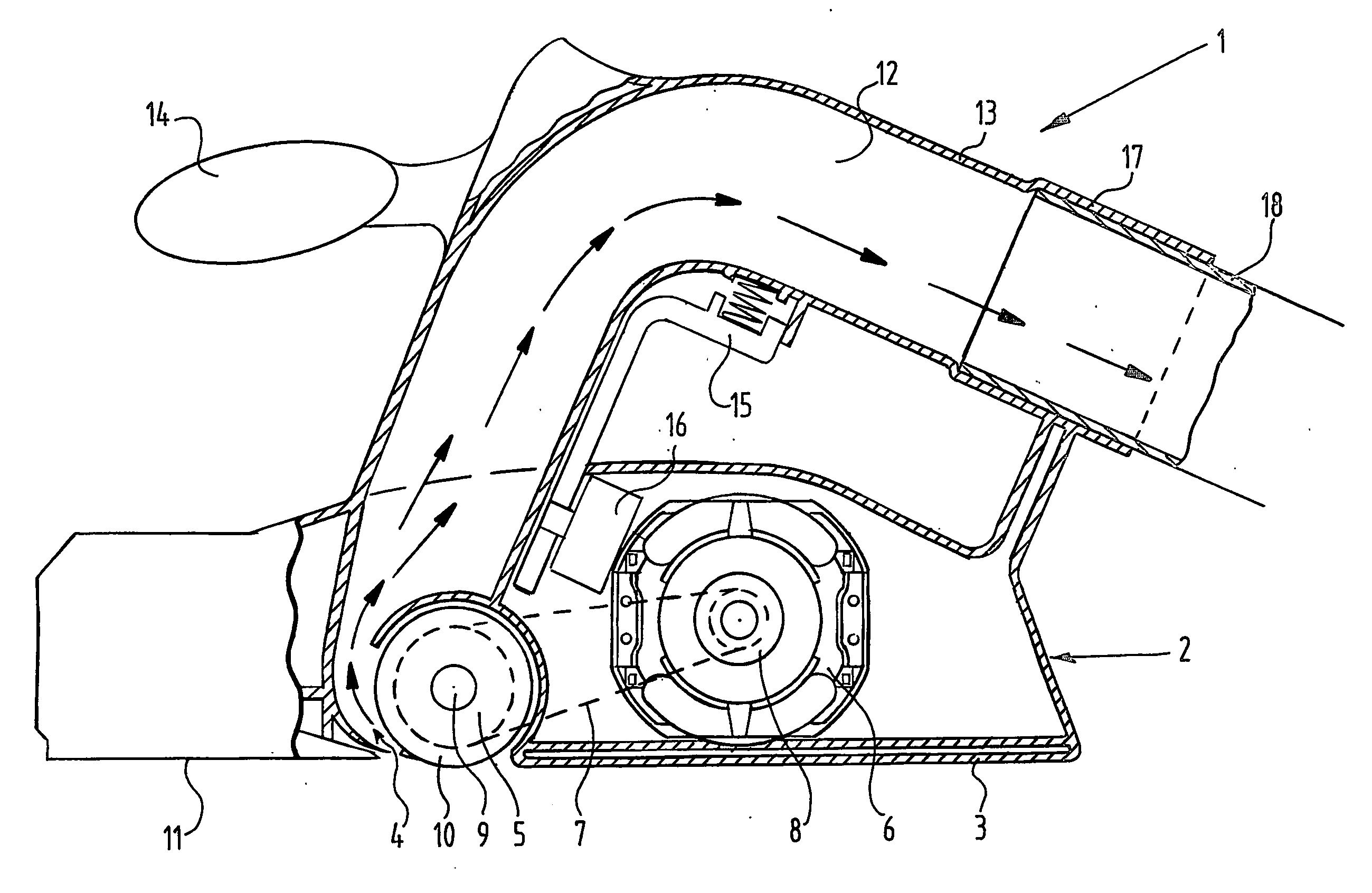
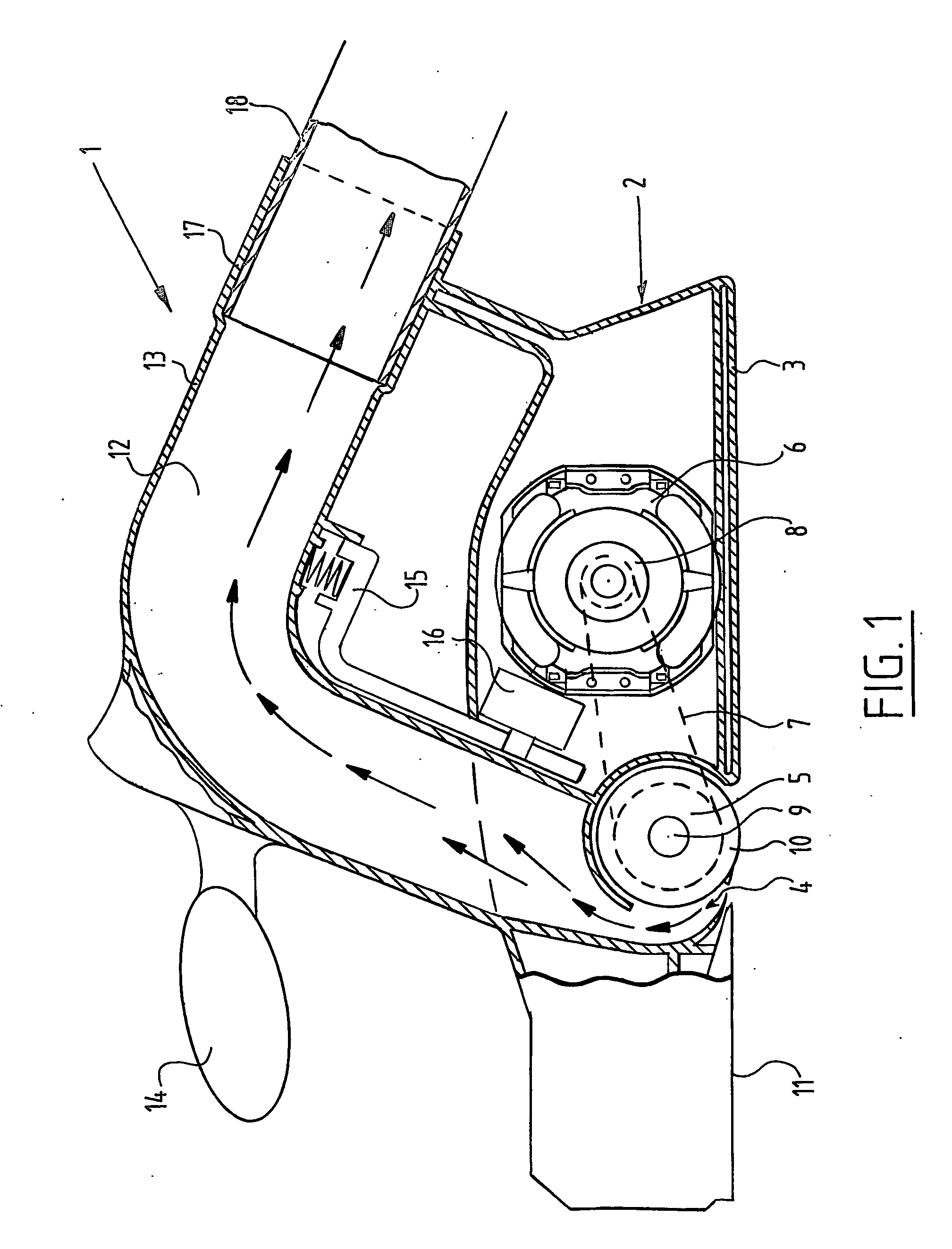
[0018]FIG. 1 shows in the form of a longitudinal section a planer designated as a whole with the reference character 1. The planer includes a housing 2 provided with a base plate 3. Recessed into the housing, in front of the base plate in the direction of movement, is a planer knife roller cavity 4 in which a planer knife roller 5 is placed. Planer knife roller 5 is mounted by a shaft 9 in bearings. The planer knife roller holder is driven by an electric motor 6 placed in the housing by a toothed belt 7 which is trained round a pulley 8 arranged on the motor shaft and a pulley 10 arranged on the planer knife roller shaft.

[0019] At the front of the housing is arranged an adjustable base 11.

[0020] The components described up to this point may all be found in conventional planers.

[0021] The planer hereof provides for the arrangement of a shavings removal channel 12 which extends through a handgrip 13 integrated into the housing. Handgrip 13 extends in the lengthwise direction of the...


PUM


Abstract

A planer includes: a housing; a motor arranged in the housing; a planer knife roller cavity arranged in the housing; a planer knife roller arranged in the planer knife roller cavity and coupled for driving to the motor; and a shavings removal channel extending in the housing from the planer knife roller cavity. The shavings removal channel extends over its whole path with a directional component in the direction of movement of the planer.

Description

FIELD OF THE INVENTION [0001] The present invention relates to a planer. The planer may include a housing, a motor arranged in the housing, a planer knife roller cavity arranged in the housing, a planer knife roller which is arranged in the planer knife roller cavity and coupled for driving to the motor, and a shavings removal channel extending in the housing from the planer knife roller cavity. BACKGROUND INFORMATION [0002] Certain planers are conventional. [0003] In such conventional planers, the shavings removal channel includes a part which extends in tangential direction and connects onto a part extending in axial direction of the planer knife roller. In certain planers, the motor is placed behind the planer knife roller. The connection of a tangential part of the channel to an axial part entails a change in direction of the airflow with the shavings entrained therein, which may reduce the effectiveness of the shavings removal. Due to the change in direction, the shavings will ...

Claims


Application Information

Patent Timeline
IPC IPC(8): B26B3/00B23Q11/00B27C1/10
CPCB27C1/10B23Q11/0042
Inventor WANNINKHOF, PETER
Owner ROBERT BOSCH GMBH
Why Eureka
Try Eureka