Protective relay capable of protection applications without protection settings

a protection relay and protection application technology, applied in the direction of circuit arrangement, emergency protection circuit arrangement, electrical equipment, etc., can solve the problems of increasing the complexity of setting tasks, challenging exercises, and increasing the difficulty of setting tasks

Inactive Publication Date: 2007-02-15
SCHWEITZER ENGINEERING LABORATORIES
View PDF1 Cites 33 Cited by
  • Summary
  • Abstract
  • Description
  • Claims
  • Application Information

AI Technical Summary

Problems solved by technology

This is often a challenging exercise.
Further, if the line protected by the relay being set can provide power and serve load in both directions from the protective relay, the setting task becomes even more complicated.
The setting task also becomes more complicated when the protection engineer must coordinate the protection provided by the relay being set with other protective relays set by another entity, an example being when utilities connect their respective power tie lines together or when utilities connect to heavy industrial loads having privately owned generators.

Method used


Image

  • Protective relay capable of protection applications without protection settings
  • Protective relay capable of protection applications without protection settings
  • Protective relay capable of protection applications without protection settings

Examples


Embodiment Construction

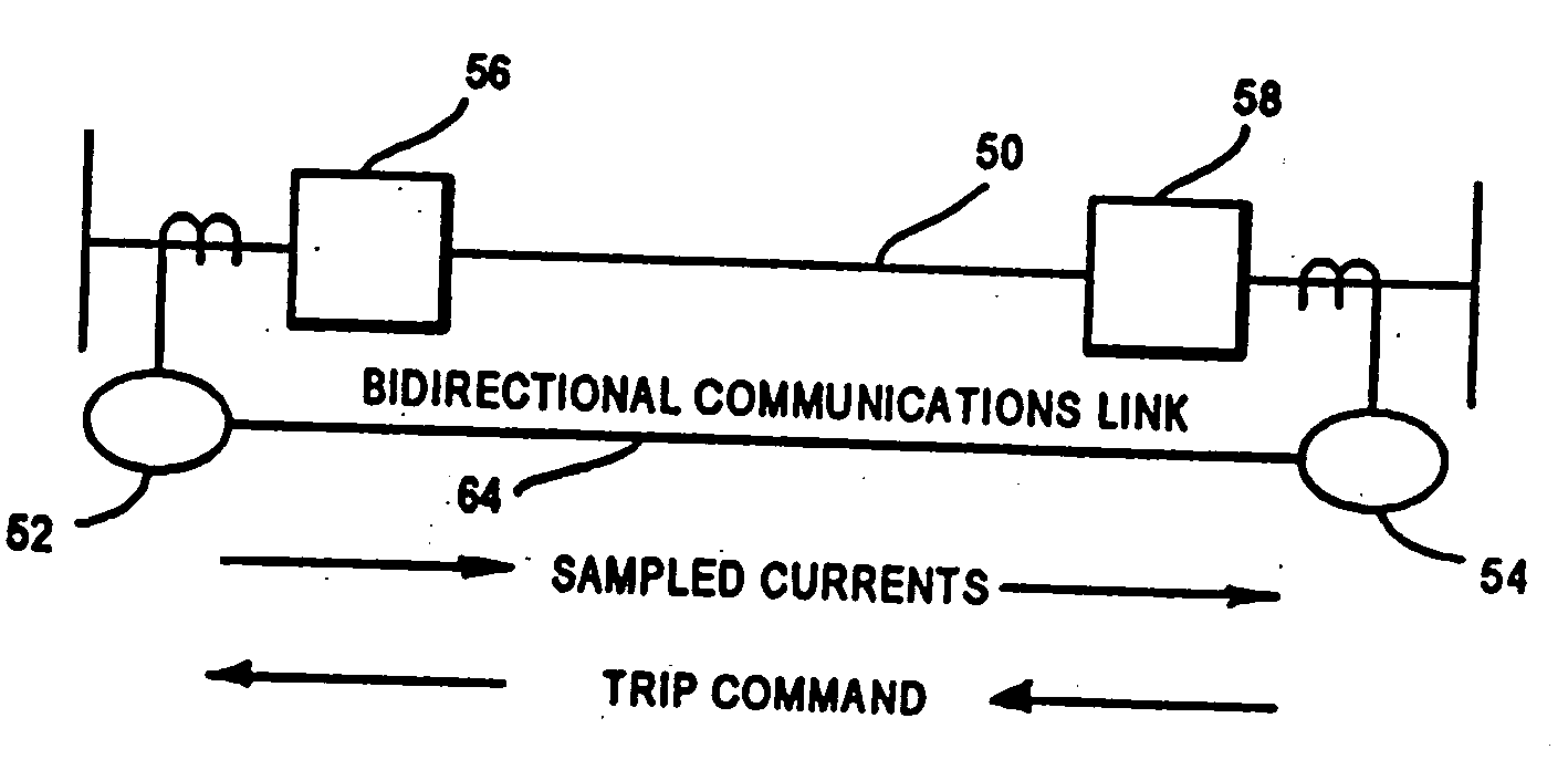
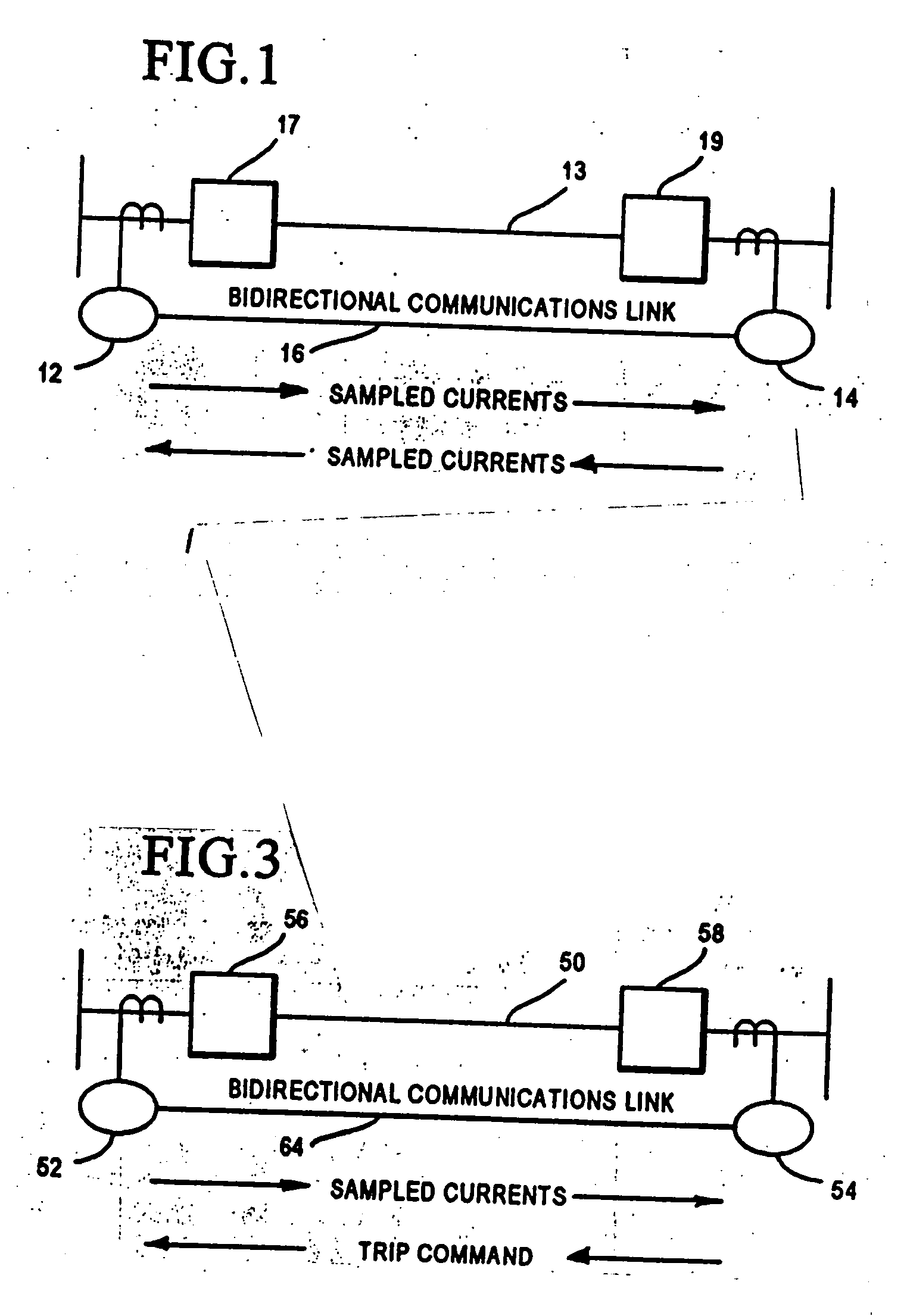
[0011] The present invention is a current differential relay without the capability of, or the need for, conventional adjustable settings. In current differential protection, referring to FIG. 1, a “local” relay 12 at one end of a protected portion 13 of a power line obtains phase currents (A, B and C phases) from the power line at that location and further receives such currents obtained by a relay at a remote end of the line, referred to as a remote relay 14. The sum of these remote and local currents is then compared with a “pickup” setting established for the particular application. Bi-directional communication occurs over a link 16, with sampled currents flowing in both directions. Circuit breakers 17 and 19 are responsive to the relays 12 and 14 to protect the line. Conventional current differential protection can also be accomplished by phase comparison of the current signals between the relative phases of the remote and local currents, and further, charge comparison, in whic...


PUM


Abstract

The current differential relay operates without adjustable settings, and includes a phase current differential element with a predetermined threshold, responsive to local phase current values and remote phase current values, to detect three-phase faults and producing a first output signal if the threshold value is exceeded. Either a negative sequence current differential element or two phase current differential elements, also having predetermined threshold values and responsive to the local and remote phase currents, detect phase-to-phase faults and phase-to-phase-to-ground faults and produces a second output signal if the predetermined threshold is exceeded. A negative sequence or zero sequence current differential current element, with a predetermined threshold value is responsive to the local and remote phase currents to detect phase-to-ground faults and to produce a third output signal if the threshold is exceeded. If any one of the first, second and third output signals occurs, a trip signal is generated and directed to the associated circuit breaker. The thresholds are selected to permit use of the relay in a wide range of possible applications.

Description

TECHNICAL FIELD [0001] This invention relates generally to protective relays for electric power systems, and more particularly concerns a current differential relay without conventional adjustable settings which is useful in the protection of a power system. BACKGROUND OF THE INVENTION [0002] Historically, digital protective relays have had an adjustable “settings” capability, which enables a protection engineer to customize the operation of a protective relay to a particular protection task in a power system. This is often a challenging exercise. For example, with a conventional overcurrent relay, the protection engineer must first determine the expected fault current and the maximum load current of the power system at the point in the system where the relay is connected. The protection engineer then establishes the operating settings of the overcurrent relay to provide a trip signal when the currents it measures from the power line reach a predetermined level above the maximum loa...

Claims


Application Information

Patent Timeline
Patent Type & Authority Applications(United States)
IPC IPC(8): H02H3/00H02H3/28H02H7/30
CPCH02H7/30H02H3/286
Inventor SCHWEITZER, EDMUND O. IIILEE, TONY J.
Owner SCHWEITZER ENGINEERING LABORATORIES
Why Eureka
Try Eureka