Method for controlling a steer-by-wire system

a technology of steering system and steer-by-wire, which is applied in the direction of steering initiation, instruments, vessel construction, etc., can solve the problems of danger to the life and limb of the driver, achieve the effect of increasing reliability and failsafe nature, facilitating plausibility checks, and high degree of protection against malfunctions

Inactive Publication Date: 2003-06-19
ROBERT BOSCH GMBH +1
View PDF2 Cites 51 Cited by
  • Summary
  • Abstract
  • Description
  • Claims
  • Application Information

AI Technical Summary

Benefits of technology

0006] A high degree of protection against malfunctions is assured by redundancy in the acquisition of measured values, control of the steering actuator and the feedback actuator, checking of all functions and components, and communications.
0007] Particularly the discrete means of acquiring various measured variables, including steering wheel angle, steering angle, restoring moment, make it easier to carry out a plausibility check of the different measured values, and to detect the occurrence of any erroneous values. This increases the reliability and failsafe nature of a steer-by-wire steering system functioning according to the present invention.
0008] Safety is further improved by redundant communication within the control device and with the vehicle's other control devices or sensors, as well as by the fact that switching from steer-by-wire operation to the auxiliary level only takes place after a transition period has elapsed following the occurrence of an error. This latter measure assures that all functions of the steer-by-wire steering system are in a defined state at the times the switch to the auxiliary level is effected.
0009] The reliability of a steer-by-wire steering method functioning ac

Problems solved by technology

Unless appropriate precautions are implemented, a fault in a steer-by-wire

Method used


Image

  • Method for controlling a steer-by-wire system
  • Method for controlling a steer-by-wire system
  • Method for controlling a steer-by-wire system

Examples


Embodiment Construction

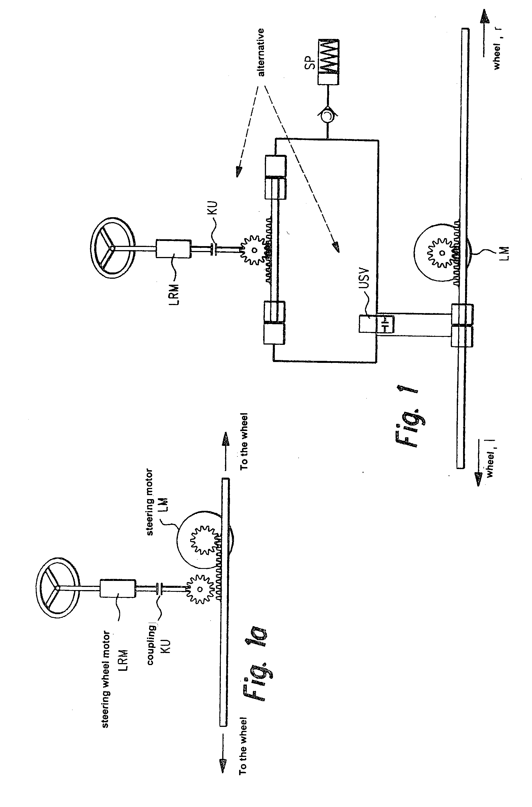
[0025] To begin with, the structure and basic functional operation of a steer-by-wire steering system having a hydraulic or mechanical auxiliary level will be described with reference to FIGS. 1 to 4. A steer-by-wire steering system having a hydraulic auxiliary level is the object of German Patent Application 198 38 490.4 of Robert Bosch GmbH.

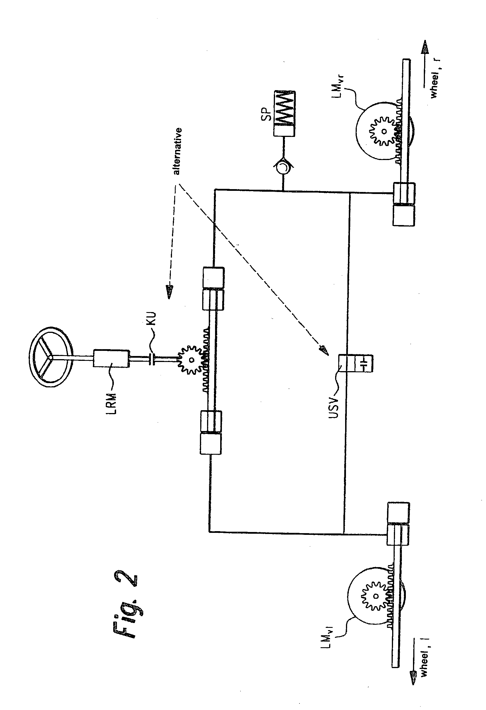
[0026] The structure shown in FIG. 1 differs from that shown in FIG. 2 in that in steer-by-wire operation with the steer-by-wire steering system of FIG. 1, the steered wheels (not shown) are moved by one steering motor LM, whereas FIG. 2 shows a variant in which two steering motors LM.sub.vl and LM.sub.vr are used.

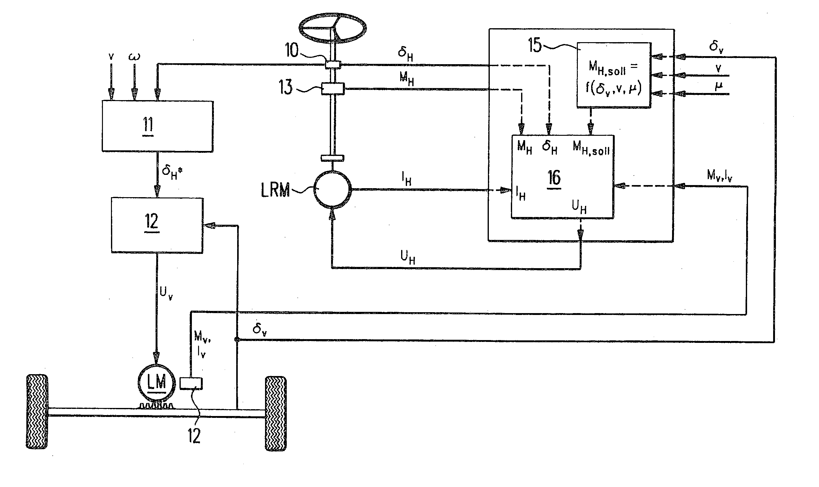
[0027] In FIGS. 1 and 2 a steering wheel motor LRM is shown, which acts as the feedback actuator for the restoring forces to be transferred to the driver through the steering wheel.

[0028] The hydraulic auxiliary level is provided by symmetrical hydraulic cylinders, a pressure reservoir SP for hydraulic fluid, and optionally a coupling...


PUM


Abstract

A device for controlling a steer-by-wire steering system in a vehicle is described. The redundantly generated sensor signals (deltav1, deltav2, deltaH1, deltaH2) for regulating a steering motor (LM) and for a feedback actuator (LRM) that transfers the restoring torques from the road to the driver via the steering wheel are received by a control device having the form of a microcomputer (RM) and plausibility checks of the sensor signals are performed therein and in an operatively associated monitoring module (ÜM). Microcomputer module (RM) and monitoring module (ÜM) monitor each other reciprocally. An auxiliary level for the steer-by-wire steering system is also monitored by the control device (RM) which, in the case of error, switches to this auxiliary level or a mechanical auxiliary level. In order to further increase the degree of safety, the steering wheel motor (LRM) is triggered via control signals (UH) for its phase currents and by a steering wheel motor enable signal (gRH), and similarly the steering motor (LM) is triggered via control signals (Uv) for its phase currents and via a steering motor enable signal (gRV). (FIG. 5)

Description

BACKGROUND INFORMATION[0001] The present invention relates to a method of controlling a steer-by-wire steering system, and a steer-by-wire steering system for vehicles, having an electronically regulated steering actuator that is attached either to the steering gear of the front axle or to both steerable front wheels, a steering wheel angle sensor that measures the driver's steering command at the steering wheel, a feedback actuator unit that provides feedback from the road to the driver through the steering wheel, a steer angle sensor for acquiring the current steering angle at the steering gear on the front axle or on the two front wheels, and a control device for acquisition of the signals transmitted by the sensors and calculation of trigger signals for the steering actuator and the feedback actuator unit.[0002] A steer-by-wire steering system is known from German Patent 195 40 956 C1. In this steering system, the mechanical connection between the steering wheel and a steering g...

Claims


Application Information

Patent Timeline
IPC IPC(8): B62D5/00B62D5/04B62D6/00B62D5/06B62D5/30B62D113/00B62D119/00
CPCB62D5/0493B62D5/003
Inventor DOMINKE, PETERCAO, CHI-THUANPFEIFFER, WOLFGANGYUAN, BOLEIMBACH, KLAUS-DIETERMUELLER, BERNDHARTER, WERNERBLESSING, PETERSCHUELE, JUERGENLOHNER, HERBERT
Owner ROBERT BOSCH GMBH
Why Eureka
Try Eureka