Power factor control for floating frame controller for sensorless control of synchronous machines

a technology of power factor control and synchronous machine, which is applied in the direction of dynamo-electric converter control, motor/generator/converter stopper, instrument, etc., can solve the problems of delay, rotor position sensor is difficult to mount to the motor, and the rotor position sensor is difficult to be reliabl

Active Publication Date: 2007-02-22
HONEYWELL INT INC
View PDF18 Cites 50 Cited by
  • Summary
  • Abstract
  • Description
  • Claims
  • Application Information

AI Technical Summary

Benefits of technology

[0014] These and other objects are substantially achieved by providing a system and method for controlling the power factor at either unity, leading or lagging, for the sensorless control of synchronous machines. The system and method commands a desired power factor (PF), either leading, lagging or unity, using a positive, negative, or unity value, respectively, and compares the desired power factor with the actual power factor feedback ((PF)fdbk) at a first adder, wherein the comparison produces a first error value. The system further operates upon the first error value with a Proportional Integrator (PI) regulator, wherein an output of the regulator is an angle command of the current Park vector in floating reference frame provided to a floating frame controller. The system and method allows the active control and change of the power factor during operation for applications such as producing the reluctance torque of a salient pole synchronous machine during Main Engine or Auxiliary Power Unit (APU) start, and field weakening of a PM machine for Environmental Control Systems (ECS) and Main Engine or APU start applications.

Problems solved by technology

However, rotor position sensors can be unreliable due to mechanical alignment problems (e.g., problems caused by bearings) and temperature incompatibility problems between the stator windings and the electronic components, such as the incorporated Hall effect devices.
Moreover, the rotor position sensors can be difficult to mount to the motor during motor assembly, especially for multi-pole motors.
However, due to the coupling impact of the motor circuitry in the floating synchronous reference frame, delays exist during transients, during which, the estimated angle of the current Park vector differs from the actual angle of the current Park vector.
Also, the coupling impact of the motor equivalent circuit in the floating synchronous reference frame forces the gain of the regulator used for angle estimation to be kept small, which slows the system response.
A further result of using a small gain is a significant delay in reducing the error between the estimated angle of the current Park vector and the actual angle of the current Park vector during slow transients, such as acceleration and deceleration, as well as fast transients, such as step changes.
Because undesirable imaginary axis current flows in the machine during these delays, longer delays may require substantial overrating of the inverter and electrical machine.
However, this method requires both ac and dc current sensors.

Method used


Image

  • Power factor control for floating frame controller for sensorless control of synchronous machines
  • Power factor control for floating frame controller for sensorless control of synchronous machines
  • Power factor control for floating frame controller for sensorless control of synchronous machines

Examples


Embodiment Construction

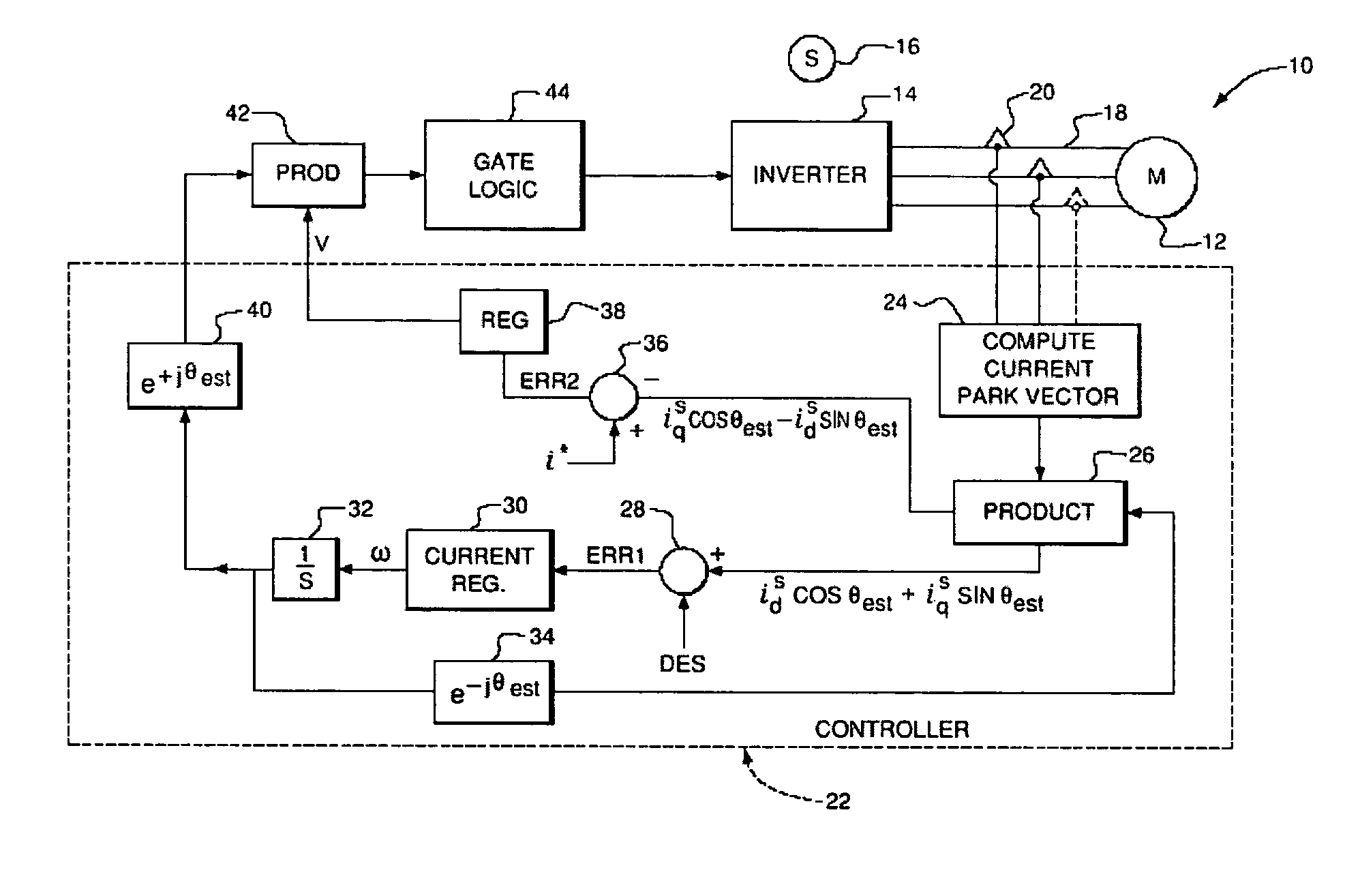
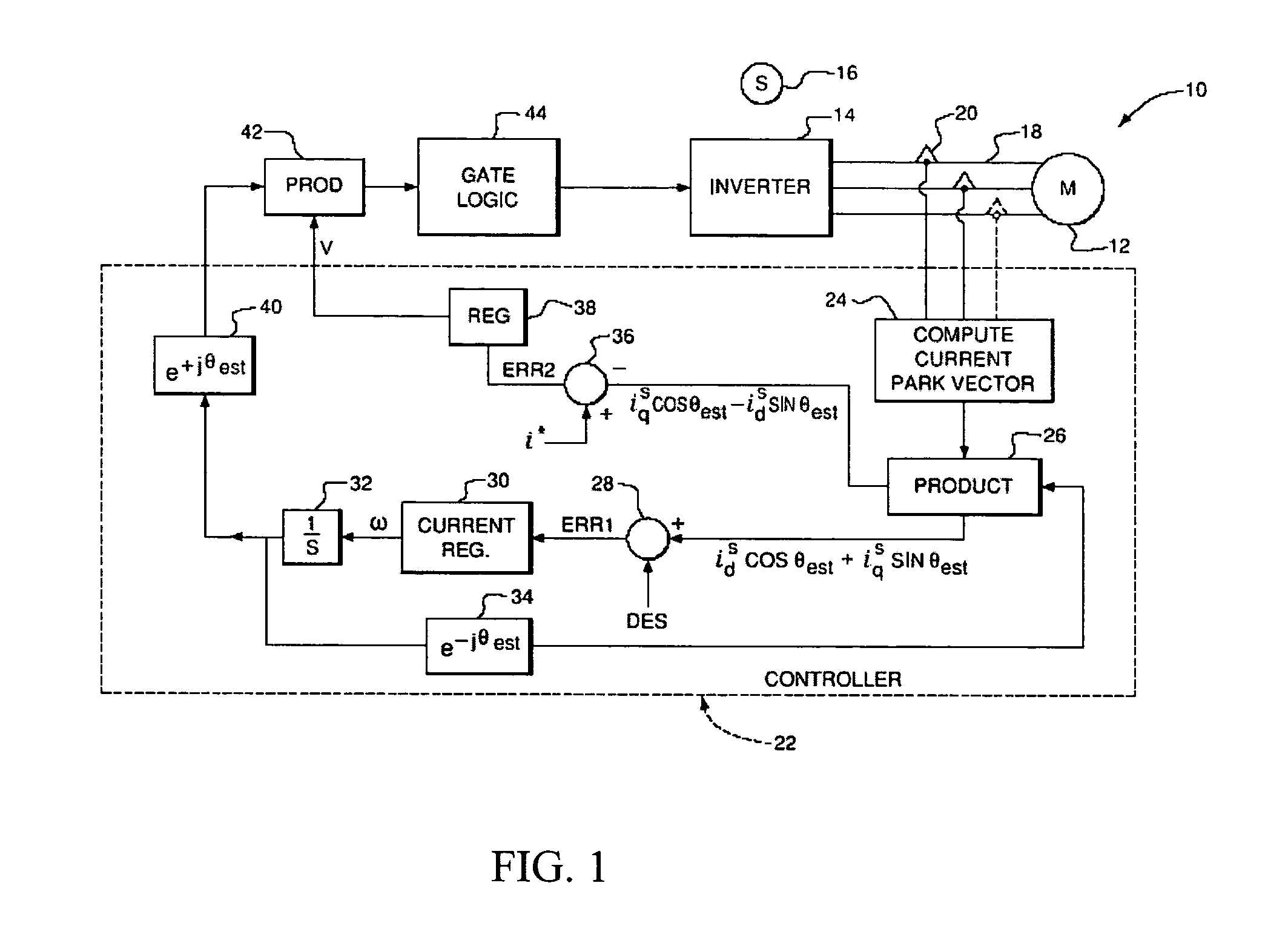
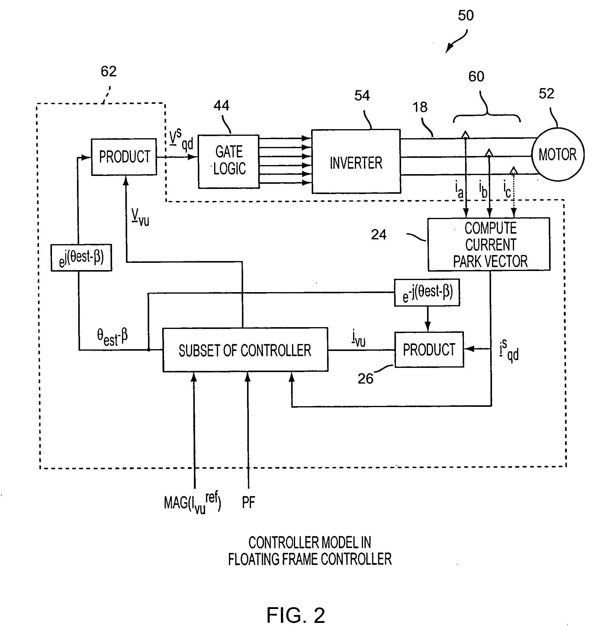
[0023] In the exemplary embodiments of the present invention described below, a power factor controller is provided for a sensorless control technique for synchronous machines by using a floating frame controller. There are various definitions of power factor depending upon the characteristics of the electrical circuit. In sinusoidal electrical systems, power factor can be defined as the angle between the terminal voltage and phase current phasors or vectors. In nonlinear systems where the applied voltage is sinusoidal, power factor can be defined as the ratio of the fundamental phase current to the RMS current.

[0024] As noted above, in prior techniques for sensorless control, the current vector is typically either in-phase with the terminal voltage vector, or not in-phase in an uncontrolled fashion due to the introduction of the decoupling of crosscoupling concept. Therefore, the power factor is unity or changes in an uncontrolled fashion due to the decoupling of crosscoupling. In...


PUM


Abstract

A system and method of controlling the power factor for providing either unity, leading or lagging results for the sensorless control of synchronous machines. The system and method provides an estimated angle of the phase current Park vector and uses a floating synchronous reference frame that is shifted from the estimated angle of the phase current Park vector by an angle β to allow the active control and change of the power factor during operation for applications such as producing reluctance torque of a salient pole synchronous machine during Main Engine Start (MES), and field weakening for Environmental Control Systems (ECS) and MES applications.

Description

CROSS-REFERENCE TO RELATED APPLICATIONS [0001] Related subject matter is disclosed in U.S. Pat. No. 6,301,136, issued on Oct. 9, 2001, entitled “Floating Frame Controller”, in U.S. patent application Ser. No. 10 / 834,857 entitled “Decoupling Of Cross Coupling For Floating Reference Frame Controllers For Sensorless Control Of Synchronous Machines”, filed Apr. 30, 2004, and in U.S. patent application Ser. No. 11 / 174,550 entitled “Enhanced Floating Reference Frame Controller For Sensorless Control Of Synchronous Machines”, filed Jul. 6, 2005, wherein the entire contents of each are incorporated herein by reference.FIELD OF THE INVENTION [0002] The present invention relates to a power factor (PF) controller for the sensorless control of synchronous machines. More particularly, the present invention relates to a system and method for the active control of power factor needed for various applications, such as achieving field weakening of Permanent Magnet (PM) synchronous machines or reluct...

Claims


Application Information

Patent Timeline
Patent Type & Authority Applications(United States)
IPC IPC(8): H02P7/36
CPCH02P21/0089H02P21/00H02P21/24H02P21/18
Inventor SARLIOGLU, BULENTHUGGETT, COLIN E.
Owner HONEYWELL INT INC
Why Eureka
Try Eureka