Unlock instant, AI-driven research and patent intelligence for your innovation.

Signal processing method for image capturing apparatus, and image capturing apparatus

a signal processing and image capturing technology, applied in the direction of color signal processing circuit, counting chain synchronous pulse counter, etc., can solve the problems of image deterioration, reduced efficiency, and increased crosstalk between adjacent pixels, so as to suppress the deterioration of color reproducibility or resolution

Inactive Publication Date: 2007-02-22
FUJIFILM CORP
View PDF6 Cites 20 Cited by
  • Summary
  • Abstract
  • Description
  • Claims
  • Application Information

AI Technical Summary

Benefits of technology

[0010] A second object of the present invention is to provide a signal processing method for an image capturing apparatus, and an image capturing apparatus, which are capable of performing signal processing in accordance with transfer efficiencies of image capturing elements and obtaining an image of a desired quality.
[0014] An image capturing apparatus according to the present invention comprises: a photographic optical system; an image capturing element onto which a subject image is formed by the photographic optical system; an image acquisition device for acquiring image signals from the image capturing element; an information acquisition device for acquiring one or more pieces of information among: transfer efficiency of the image capturing element, sensitivity of a camera upon photography, a drive frequency of the image capturing element, a WB parameter related to white balance correction of the acquired image signal, a number of pixels of the acquired image signal, an interior temperature of the camera or the temperature of the image capturing element upon photography, a CCD color filter array of the image capturing element, wherein the information acquisition device acquires at least the transfer efficiency; and a signal processing device for performing signal processing on the acquired image signals, the signal processing device which changes signal processing according to the acquired information to suppress deterioration of image quality due to degradation of the transfer efficiency.
[0019] The transfer efficiency calculation step performs calculations based on signals of pixels in an effective pixel region and signals of pixels in an optical black region of the image capturing element. In addition, the transfer efficiency calculation step according to the other aspect performs calculations based on signals of each single pixel on either side (in a horizontal direction) of a vertical boundary of the effective pixel region and the optical black region of the image capturing element, or on signals of a plurality of pixels in vertical directions of each single pixel on either side of the vertical boundary of the image capturing element. When using signals from a plurality of pixels of the effective pixel region-side and a plurality of pixels of the optical black region-side, the signals of each pixel will be averaged, enabling calculation of transfer efficiency at high accuracy.
[0035] According to the present invention, deterioration of color reproducibility or resolution may be suppressed regardless of transfer efficiencies of image capturing elements, even when, for instance, transfer efficiencies decrease, and a desired image quality may be maintained. In addition, transfer efficiencies of image capturing elements may calculate to enable image processing corresponding to the transfer efficiencies to be performed on image signals acquired from the image capturing elements. This allows images of a desired image quality to be obtained regardless of transfer efficiency.

Problems solved by technology

When the transfer efficiency is reduced, crosstalk between adjacent pixels increase, and various problems such as image deterioration (deterioration of color reproducibility or resolution) occur.

Method used


Image

  • Signal processing method for image capturing apparatus, and image capturing apparatus
  • Signal processing method for image capturing apparatus, and image capturing apparatus
  • Signal processing method for image capturing apparatus, and image capturing apparatus

Examples


fifth embodiment

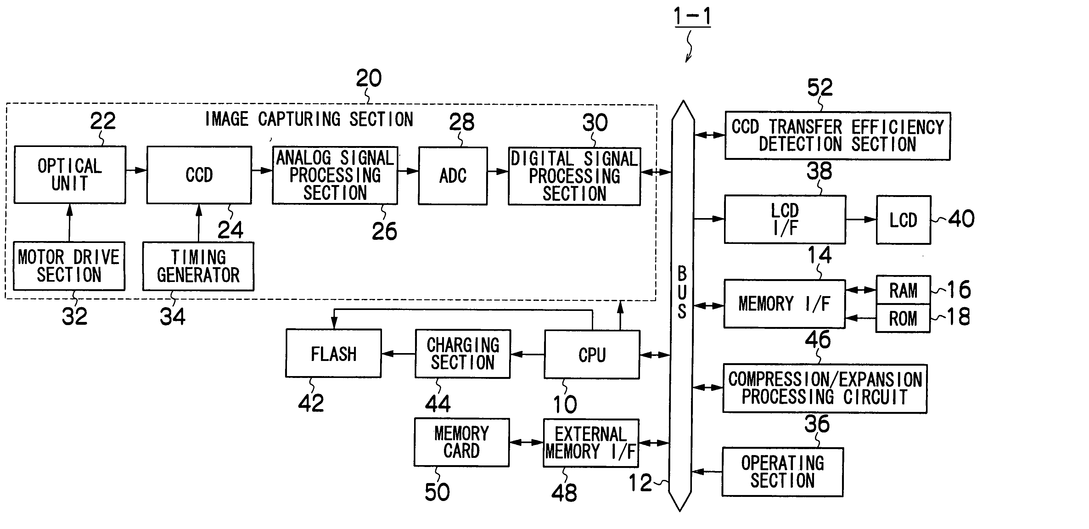
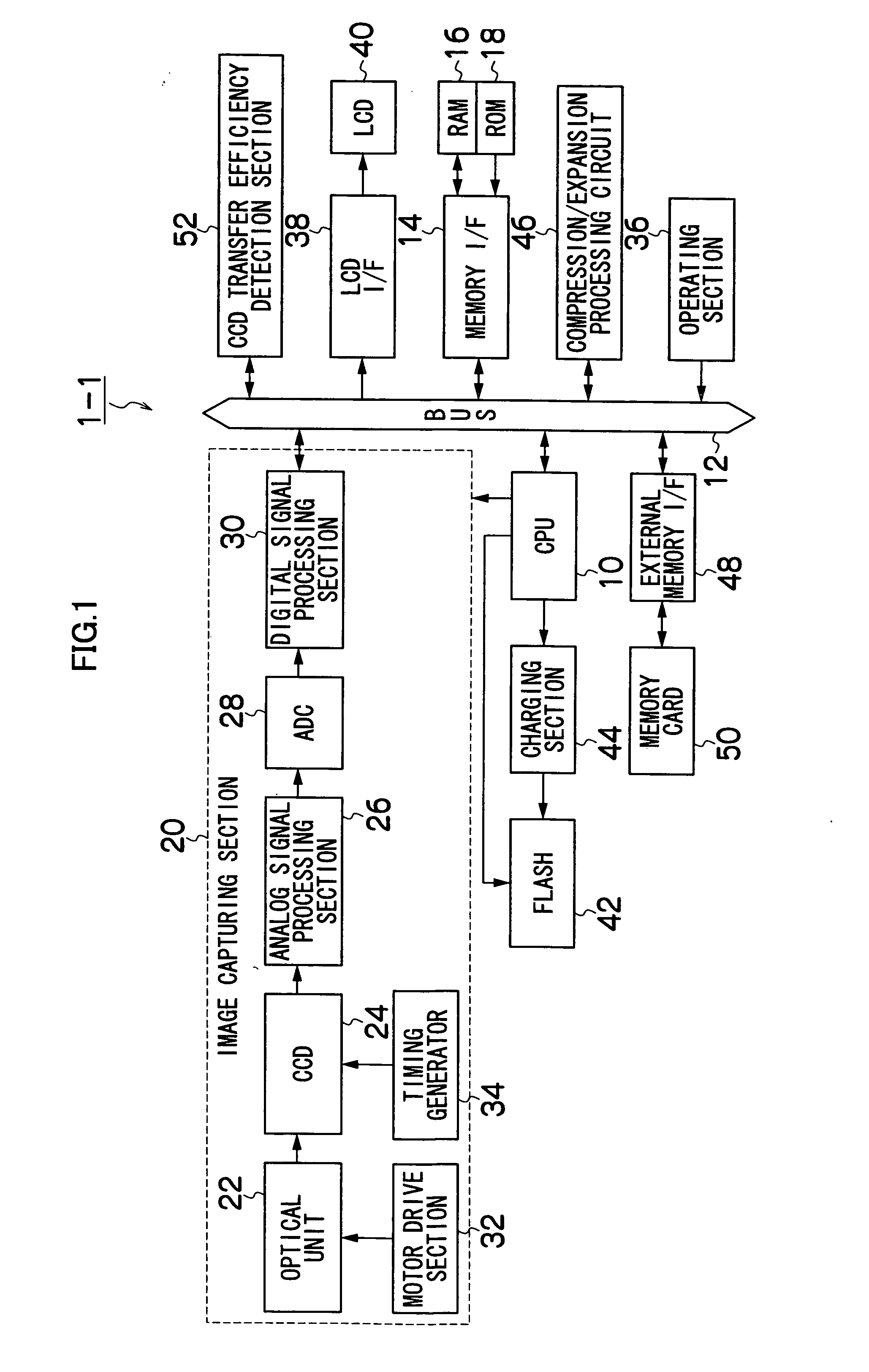
[0172]FIG. 13 is a block diagram showing a fifth embodiment of an image capturing apparatus according to the present invention. Incidentally, like portions to the block diagram of the first embodiment shown in FIG. 1 are assigned like reference characters, and detailed descriptions thereof will be omitted.

[0173] A camera 1-5 of the fifth embodiment shown in FIG. 13 differs from the camera 1-1 of the first embodiment in that the camera 1-3 further comprises a pixel count detection section 62.

[0174] The pixel count detection section 62 detects a pixel count (VGA, 1 M, 3 M, 6 M and the like) during photography. The digital signal processing section 30 performs signal processing based on the transfer efficiency acquired from the CCD transfer efficiency detection section 52 and the pixel count detected by the pixel count detection section 62 so as to suppress image quality deterioration caused when the transfer efficiency drops below normal transfer efficiency.

[0175] In the present em...

sixth embodiment

[0186]FIG. 16 is a block diagram showing a sixth embodiment of an image capturing apparatus according to the present invention. Incidentally, like portions to the block diagram of the first embodiment shown in FIG. 1 are assigned like reference characters, and detailed descriptions thereof will be omitted.

[0187] A camera 1-6 of the sixth embodiment shown in FIG. 16 differs from the camera 1-1 of the first embodiment in that the camera 1-6 further comprises a temperature detection section 64.

[0188] The temperature detection section 64 detects a temperature of the CCD 24. Incidentally, when the temperature of the CCD 24 cannot be detected directly, the temperature detection section 64 may be arranged to detect an internal temperature of the camera chassis as a temperature corresponding to the temperature of the CCD 24.

[0189] The digital signal processing section 30 performs signal processing based on the transfer efficiency acquired from the CCD transfer efficiency detection sectio...

seventh embodiment

[0198]FIG. 18 is a block diagram showing a seventh embodiment of an image capturing apparatus according to the present invention. Incidentally, like portions to the block diagram of the first embodiment shown in FIG. 1 are assigned like reference characters, and detailed descriptions thereof will be omitted.

[0199] A camera 1-7 of the seventh embodiment shown in FIG. 18 differs from the camera 1-1 of the first embodiment in that the camera 1-7 further comprises a CCD array detection section 66.

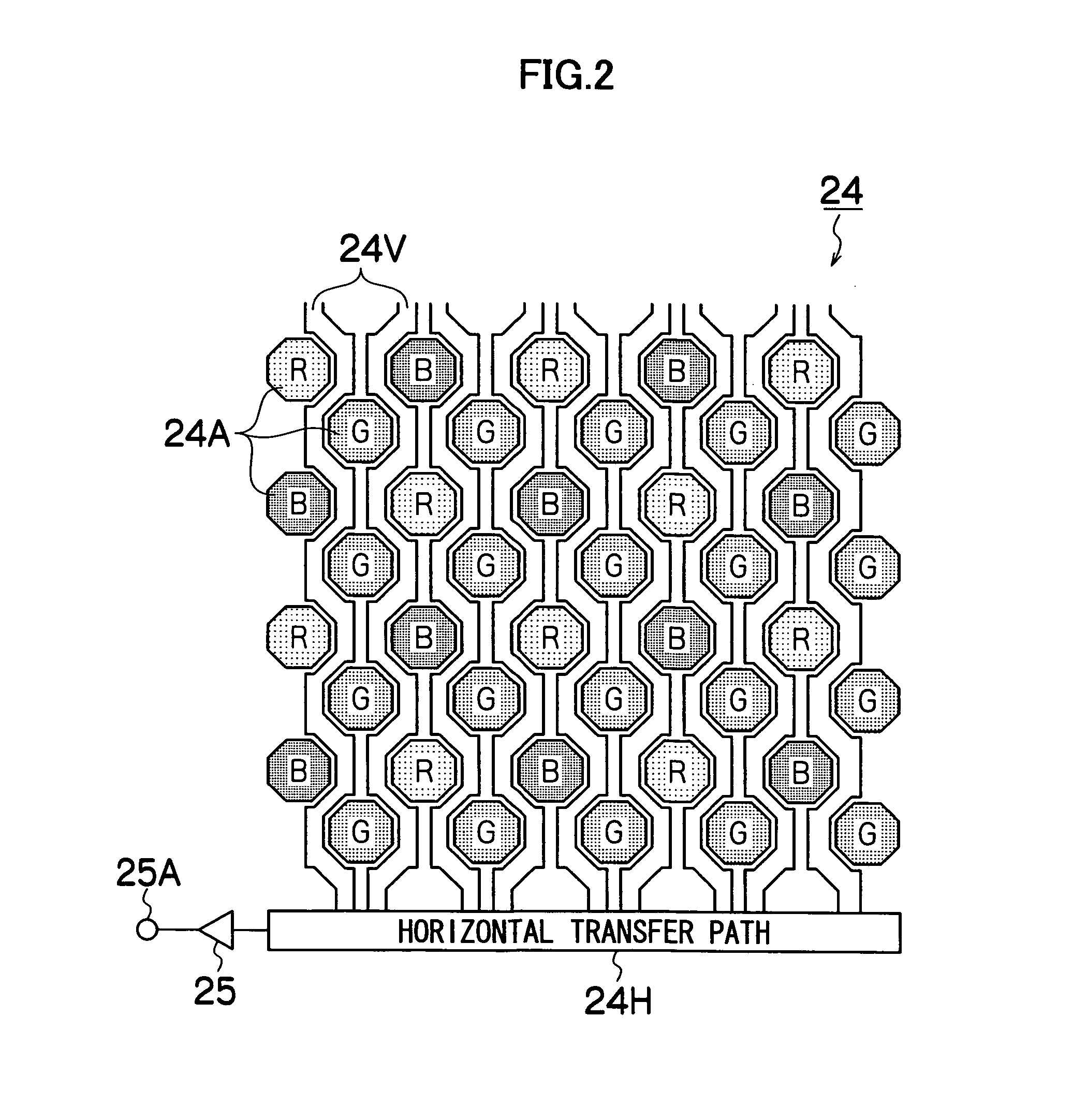
[0200] The CCD array detection section 66 detects CCD arrays of the CCD 24. The CCD array of the CCD 24 is determined in advance according to the CCD. Therefore, since the color sequence of the R, G, B dot-sequential CCD signals outputted from the CCD 24 is already known, the CCD array detection section 66 may be configured so as to store information related to the CCD array of the CCD 24 (for instance, G-stripe R / G full-checkered pattern or Bayer array), and read out the information as neede...


PUM


Abstract

The present invention provides an image capturing apparatus which enables a desired image quality to be maintained regardless of transfer efficiency of a CCD image capturing element. R, G and B signals (CCD-RAW data) are acquired from the CCD image capturing element. In addition, various information, namely transfer efficiency of the CCD image capturing element, camera sensitivity upon photography, drive frequency of the CCD image capturing element, WB gains of the acquired R, G and B signals, pixel count, internal temperature of camera or temperature of the CCD image capturing element, and CCD color filter array of the CCD image capturing element are acquired. Signal processing on the acquired R, G and B signals is changed according to the acquired information in order to suppress image quality deterioration due to transfer efficiency degradation.

Description

BACKGROUND OF THE INVENTION [0001] 1. Field of the Invention [0002] The present invention relates to a signal processing method for an image capturing apparatus, and an image capturing apparatus. In particular, the present invention relates to a technique for remedying problems due to insufficient transfer efficiency of CCD (charge coupled devices) image capturing elements. [0003] 2. Description of the Related Art [0004] Conventionally, image capturing apparatuses using CCD image capturing elements, such as electronic cameras, digital cameras and camera-equipped mobile phones, have been developed. When performing image capturing using such an image capturing apparatus, signal charges are accumulated in each pixel of a CCD image capturing element according to exposure time. Signal charges accumulated in each pixel are transferred from a vertical transfer path to a horizontal transfer path, and are outputted to an image processing circuit. [0005] Signal charges accumulated in each pix...

Claims


Application Information

Patent Timeline
IPC IPC(8): H04N5/228G03B13/00H04N5/357H04N5/372H04N5/378H04N9/04H04N9/73
CPCH04N1/6086H04N5/361H04N5/37213H04N9/045H04N9/735H04N17/002H04N25/70H04N25/713H04N23/843H04N25/11H04N23/88H04N25/633H04N25/63
Inventor ASHIDA, TETSUROIRIE, KOUSUKEYAMASHITA, HITOSHIUEDA, TOORUHAYASHI, KENKICHIMIYASHITA, TAKESHI
Owner FUJIFILM CORP