System to reduce the pressure drop in a differential mobility analyzer

a technology of differential mobility analysis and differential mobility analysis, which is applied in the direction of instruments, particle separator tube details, separation processes, etc., can solve the problems of reducing the resolution of instruments, limiting the brownian diffusion factor to achieve high resolution in the nanometric range, and reducing the efficiency of instruments. , to achieve the effect of deteriorating resolution and high efficiency

Inactive Publication Date: 2011-12-06
CENT DE INVESTIGACIONES ENERGETICAS MEDIO AMBIENTALLES Y TECNOLOGICAS (C I E M A T)
View PDF12 Cites 0 Cited by
  • Summary
  • Abstract
  • Description
  • Claims
  • Application Information

AI Technical Summary

Benefits of technology

[0009]The DMA comprises a high efficiency filter, which allows the sheath flow to be particle free and uniformly distributed. After going through a laminarization screen and a convergent section, the sheath flow rate goes through the particle classification section. Downstream, the gas is extracted in the axial direction after going through a first Teflon drilled piece. This piece allows the sheath gas extraction system to have a single outlet chamber and it is at the same time the inner electrode support and an electrical isolator, adapted to fit in the DMA inner electrode piece. Downstream, the gas is finally extracted by a second Teflon convergent piece and a third metallic cone shape piece. The objective of this last piece is to avoid flow instabilities which could be propagated upstream thus deteriorating the resolution.
[0012]As a consequence, the outlet flow is characterized by an axilsymmetry flow and with no restriction to this flow producing a low pressure drop and this allows the attainment of high flow rates using a moderate pumping capacity.
[0013]The sheath gas extraction system to reduce the pressure drop in a differential mobility analyzer (DMA) is able to cover the 1-600 nm range, reaching resolutions around 12 for the smallest size and working at high flow rates.

Problems solved by technology

This can only be reached with high resolution instrumentation.
However, the limiting factor to reach high resolution in the nanometric range is Brownian diffusion.
In case of appearance of turbulence, the instrument resolution would be drastically degraded.
This means a high pressure drop, which preempts high flow rates and high resolutions.
All these problems have forced the use two different DMAs to cover the 1-600 nm size range, because one instrument was not able to cover it with enough and adequate resolution.

Method used


Image

  • System to reduce the pressure drop in a differential mobility analyzer
  • System to reduce the pressure drop in a differential mobility analyzer
  • System to reduce the pressure drop in a differential mobility analyzer

Examples


Embodiment Construction

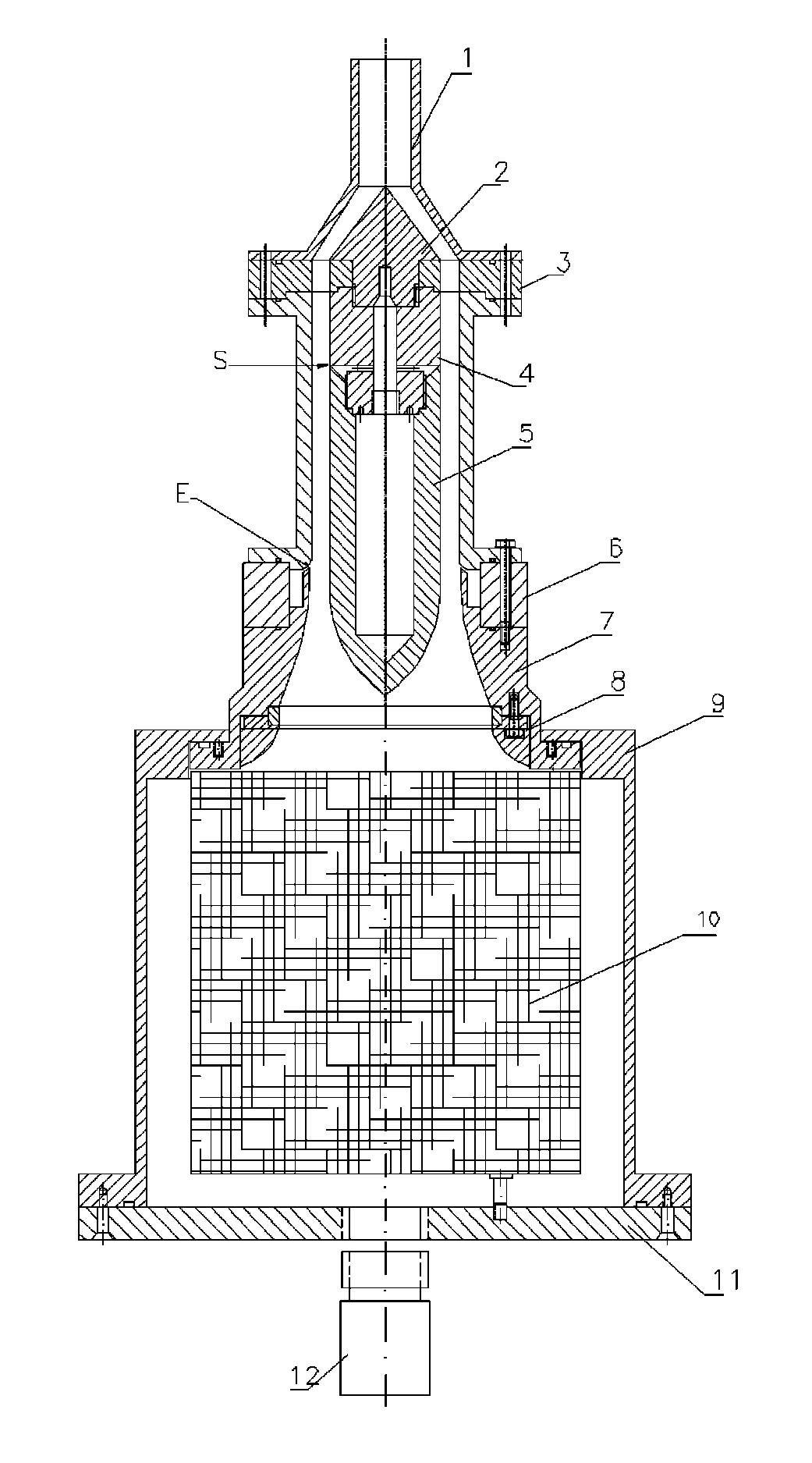
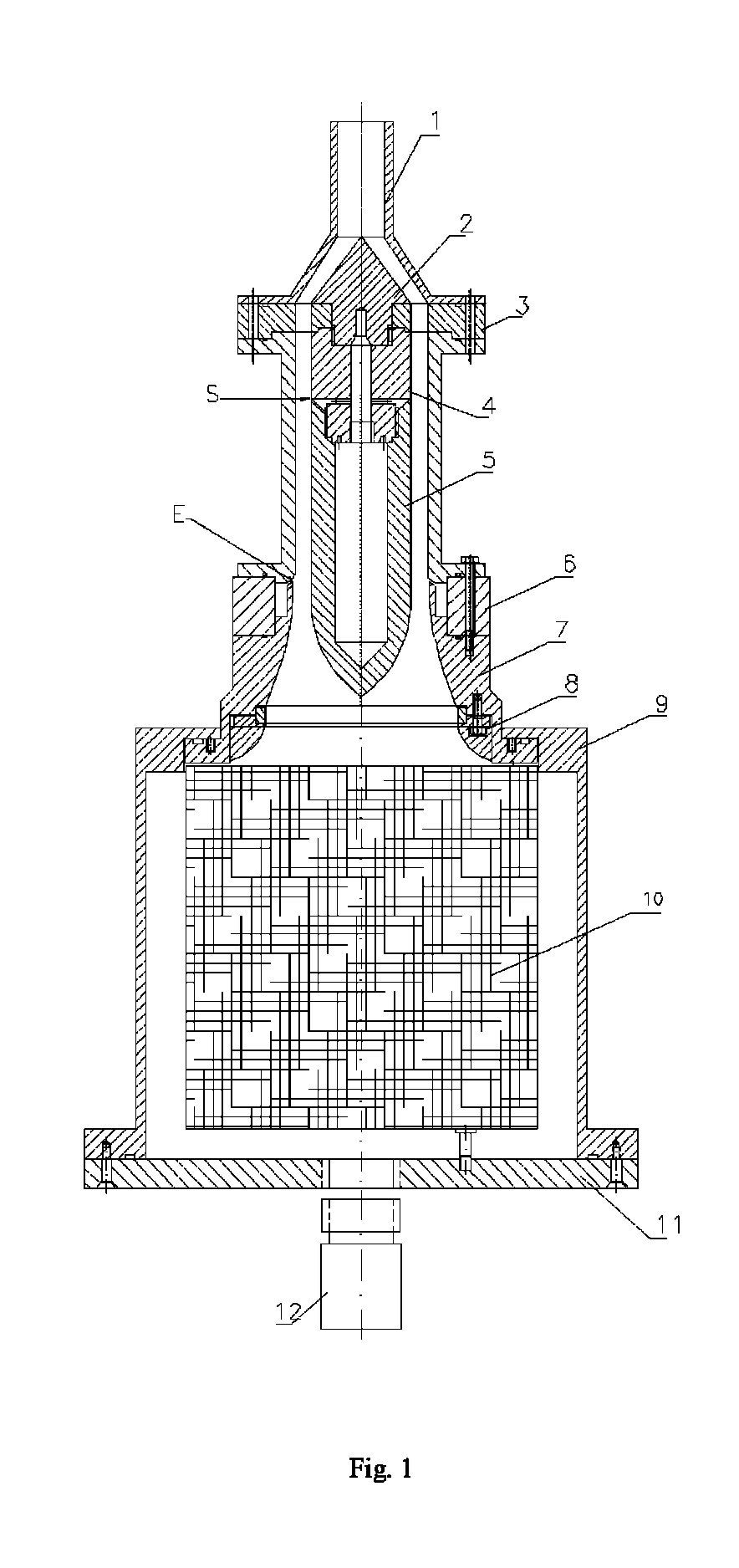
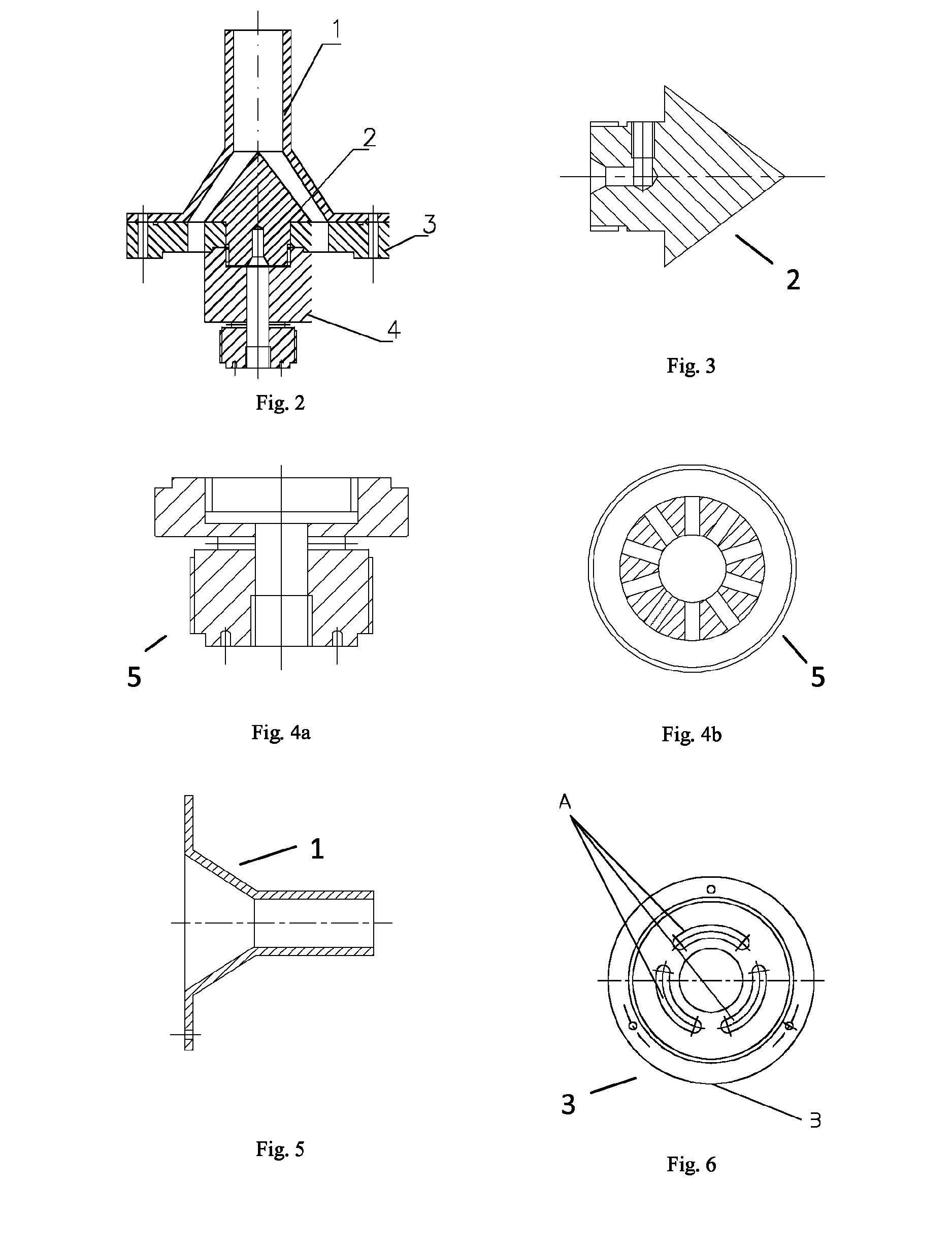
[0024]The sheath gas extraction system (FIG. 2) is formed by a circular Teflon piece (3), with three concentric slots (A) showed in FIG. 6. The sheath gas goes axially through these slots (A). There is a fourth orifice, radially machined where the monodisperse gas outlet tube is inserted (B). This tube is screwed to the metallic conic piece (2), located downstream the piece (3). At the same time, the inner electrode support (4) is screwed to the conic piece (2), resting the Teflon piece (3) between the conic piece (2) and the inner electrode support (4). After assembling, these pieces (FIG. 2) are supported in the outer electrode (6 in FIG. 1). Finally, the Teflon piece (1) is screwed to the set.

[0025]FIGS. 3-5 show different pieces the system: In FIG. 3 it is shown the cone located downstream designed to stabilize the flow after the piece (3) (FIG. 6). In FIGS. 4a and 4b there are shown a lateral and sectional view of the piece located upstream of piece 3 (FIG. 6), through which th...


PUM

PropertyMeasurementUnit
arc angleaaaaaaaaaa
outer radiusaaaaaaaaaa

Abstract

System to reduce the pressure drop in a Vienna-type differential mobility analyzer (DMA). It is built to favor the flow axilsymmetry, with no restrictions to avoid strong pressure drops and high pumping capacities. It comprises an electrical isolator, a metallic cone to stabilize the flow, all in one instrument covering a size range of 1 to 600 nm. The electrical isolator is capable of a potential difference of up to 14 kV. It can be used to measure ions and particles in the size range already mentioned with resolutions up to 12.

Description

TECHNICAL FIELD OF THE INVENTION[0001]The present invention refers to a device able to measure ions and particles from 1 nm up to 600 nm, with resolution of up to 12. This is achieved by decreasing the pressure drop in Vienna-type Differential Mobility Analyzers (DMAs) (Winklmayr et al., 1991). Such size range is reached with a moderate pumping capacity, such as a vacuum pump. At the same time, the device allows up to a 14-kV potential difference, and thus is able to measure particles of several hundred nanometers.BACKGROUND OF THE INVENTION[0002]DMAs (Differential Mobility Analyzers) classify charged particles based on their capacity to migrate in an electric field. A DMA basically works by introducing a charged particle sample in a clean gas flow, which drags them through a region where there is an electrical field. The combination of the electrical and the flow fields classify the particles as a function of their electrical mobility. At the same time, this is a function of the pa...

Claims


Application Information

Patent Timeline
Patent Type & Authority Patents(United States)
IPC IPC(8): H01J49/06G01N1/22
CPCG01N15/0266G01N2015/0038
Inventor GOMEZ MORENO, FRANCISCO JAVIERMARTINEZ LOZANO SINUES, PABLOMARTIN ESPIGARES, MANUEL
Owner CENT DE INVESTIGACIONES ENERGETICAS MEDIO AMBIENTALLES Y TECNOLOGICAS (C I E M A T)
Why Eureka
Try Eureka