This helps you quickly interpret patents by identifying the three key elements:
Problems solved by technology
Method used
Benefits of technology
Benefits of technology
[0016] Accordingly, the present invention has been made keeping in mind the above problems occurring in the prior art, and an object of the present invention is to provide a prefabricating rack frame in which no special fastening means such as bolt and nut are used for the assembly of a column and a cross member, and more than 2 couplings are provided at the assembly of a column and a cross member. The present invention has more rigid assembly force t
Problems solved by technology
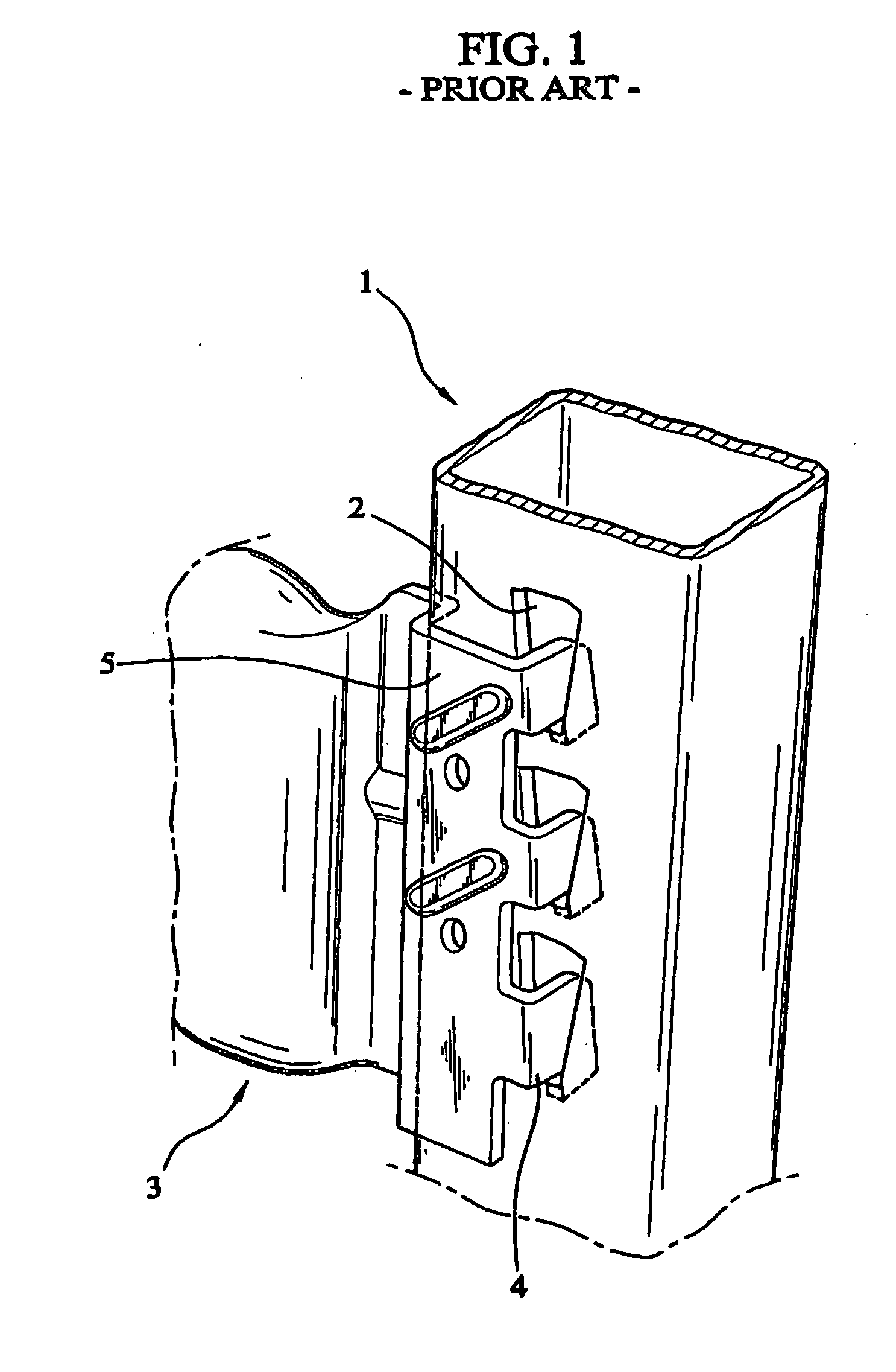
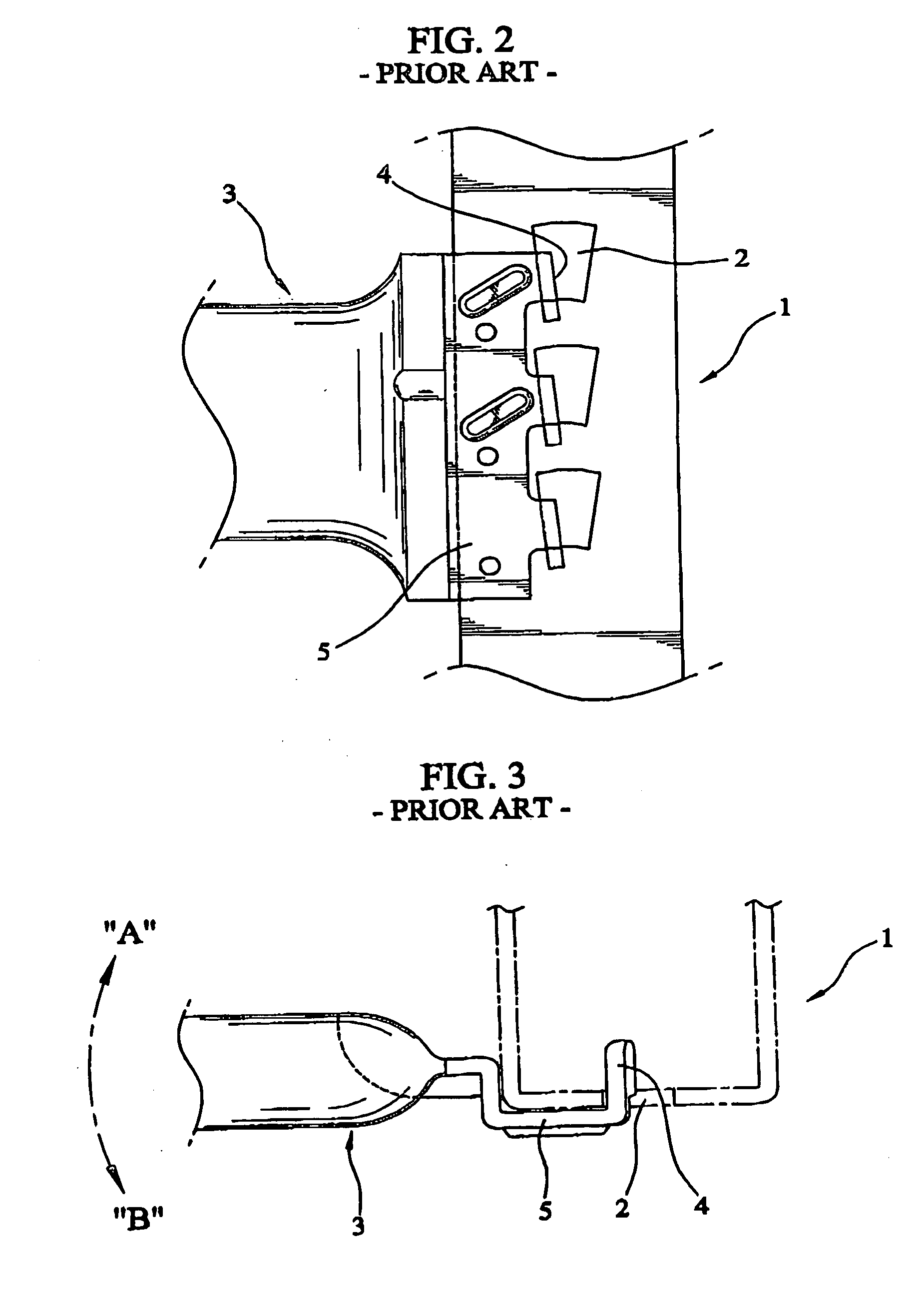
However, such a prefabricating shelf needs plural bolts and nuts to lead troublesome in assembly and disassembly and needs much work time.
This brings an increase of cost.
Furthermore, angles can be distorted by load of goods placed on the shelf after long-term usage.
That causes plenty of problems such as an ugly appearance and instability.
However, the conventional art needs to have a gap between the hook and the slot when the hook is inserted into the slot, because it would lead to a difficult assembly if there was no gap.
The gap causes a
Method used
Image
Click on the blue label to locate the original text in one second.
Reading with bidirectional positioning of images and text.
Examples
Example
[0047] In the first embodiment shown in FIGS. 5 to 10, the inner slots 11a of the column 10 are arranged in 2 vertical rows, and in the form of the 3 horizontal rows along the upper and lower side. This illustrates that the shape of the inner and outer slots 11a, 11b have a vertical rectangular form and each bottom of the rectangle slants to the vertical center line of the one side of the column 10 (FIG. 7).
[0048] Such a column 10 is made by a square tube having a thick thickness, and is used for a large size prefabricating rack frame to sustain a relatively heavy load.
Example
[0049] In the fourth embodiment shown in FIGS. 13 to 16, the inner slots 11a of the column 10 are arranged in one vertical row, and in the form of three horizontal rows in the upper and lower side. This illustrates that the shape of the inner slots 11a have a reverse trapezoid form having a longer upper width and a shorter lower width (FIG. 15).
[0050] The inner slot 11a of the column 10 can receive each outer hook 22b of the cross member 20 when each cross member 20 is inserted into respective side end of the column 10 as shown in FIG. 15. This configuration can be adapted to the cross member which is made by a relatively thin thickness pipe. That is used for a prefabricating rack frame of small and medium size to sustain light load.
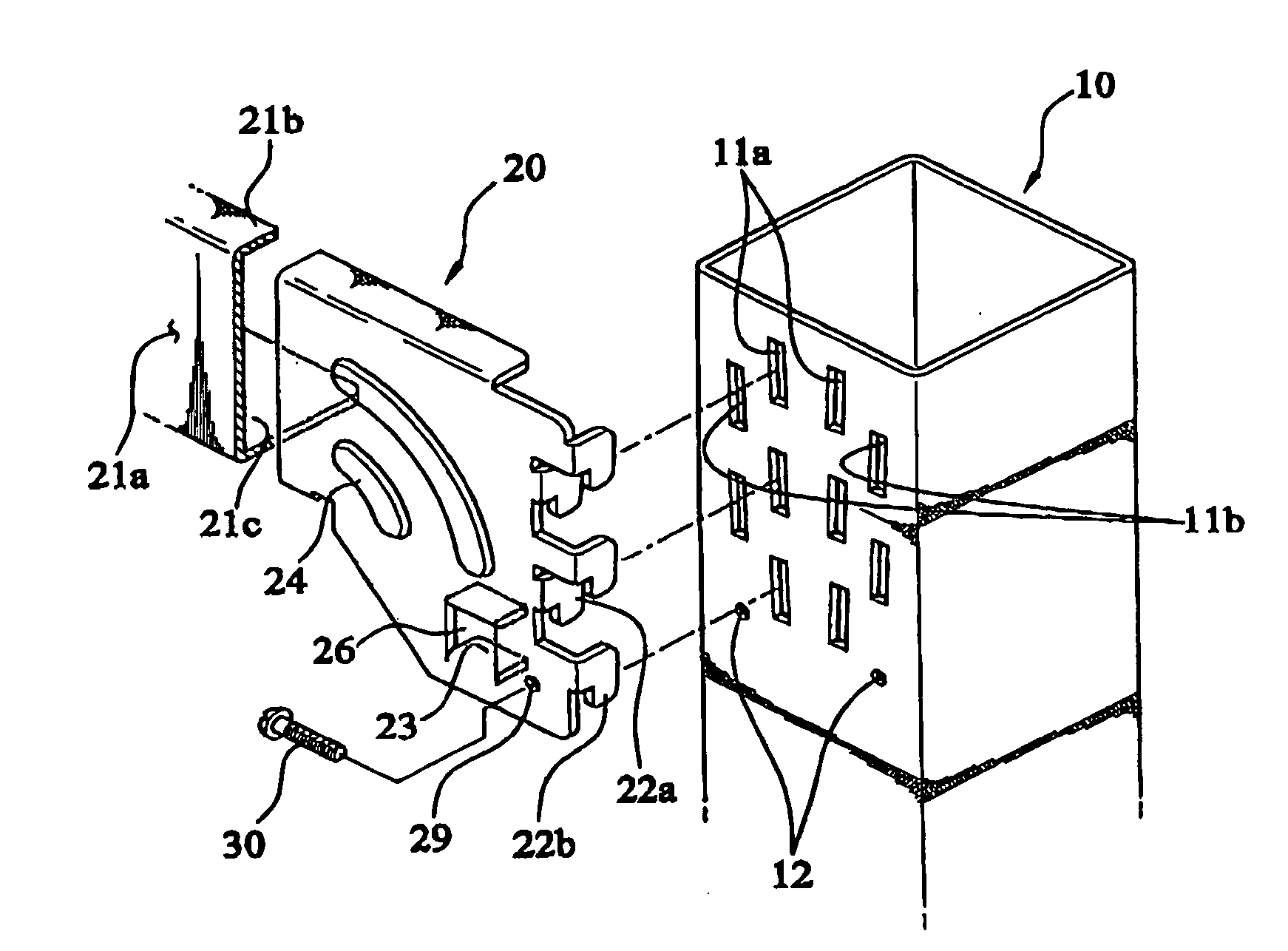
[0051] The cross member 20 is comprised of a vertical web 21a, an upper / lower horizontal flange 21b, 21c, plural inner / outer hooks 22a, 22b, and a location restrictor 23. The inner / outer hooks 22a, 22b are formed at each longitudinal end of the vertica...
Example
[0076] Hereafter, the technical components of the fifth embodiment will be described below with reference to FIGS. 17 to 21.
[0077] The column 110 is made of a thick material. The inner slots 111a, 111b are formed along a longitudinal direction. Each inner slot 111a, 111b has a distance L1, L2 from a center line Y of the body 110a. The outer slots 112a, 112b are provided at the outer side of each inner slot 111a, 111b and are provided between an upper inner slot 111a, 111b and a next below inner slot 111a, 111b at a predetermined interval. A pair of round openings 113a, 113b is provided below the lowest outer slot 112a, 112b.
[0078] The inner slot 111a, 111b and the outer slot 112a, 112b are configured, as shown in FIG. 18, as a vertical rectangular. Each vertical rectangular slants to a center line Y of the body 110a at a predetermined angle α1, α2, and the longitudinal line of each vertical rectangular is directed to the center line Y.
[0079] The cross member 114 hooked into the c...
PUM
Abstract
The prefabricating rack frame are comprised of a column and a cross member. The column is comprised of plural inner slots and plural outer slots. The inner slots are arranged in one or two vertical row in the center. The outer slots are formed at the respective outer side of each line of the inner slot, and each outer slot is located between the upper and lower row of the inner slot at equal interval. A location restrictor of the cross member is bent parallel to the upper horizontal flange, by which the location restrictor is fully contacted on the side surface of the column along the upper horizontal flange. A hole is provided at the vertical web so as to overlap any of the round openings. The round openings and the hole are for engaging the column and the cross member by the screw.
Description
TECHNICAL FIELD [0001] This invention relates to a prefabricating rack frame that can be installed at a store, or warehouse, and a library, and on which different types of goods can be placed. The invention, specially, relates to the prefabricating rack frame that is made of only a column and a cross member without additional components, therefore, shakes can be prevented and structural stability can be attained. BACKGROUND ART [0002] Most shelves can be used for storing or displaying goods in all kinds of mart or warehouse. The shelf has a structure in which several plates are stacked at a predetermined interval, and is composed by prefabrication for a facility of portage, assembly and disassembly. [0003] Generally, to establish a prefabricating rack, an angle having plural slots can be cut at a predetermined length, and the angle is fastened by bolts and nuts through the bracket attached on the angle, thus making a shelf frame. A shelf, made of thin steel or wood plate, is placed ...
Claims
Application Information
Patent Timeline
Application Date:The date an application was filed.
Publication Date:The date a patent or application was officially published.
First Publication Date:The earliest publication date of a patent with the same application number.
Issue Date:Publication date of the patent grant document.
PCT Entry Date:The Entry date of PCT National Phase.
Estimated Expiry Date:The statutory expiry date of a patent right according to the Patent Law, and it is the longest term of protection that the patent right can achieve without the termination of the patent right due to other reasons(Term extension factor has been taken into account ).
Invalid Date:Actual expiry date is based on effective date or publication date of legal transaction data of invalid patent.

