
Integrated containment system

a containment system and integrated technology, applied in auxillary pretreatment, separation processes, instruments, etc., can solve the problems of large space and cost of installation, high material cost, and large volume of the conventional containment system

Active Publication Date: 2007-03-01
CAMFIL USA
View PDF16 Cites 28 Cited by
  • Summary
  • Abstract
  • Description
  • Claims
  • Application Information

AI Technical Summary

Benefits of technology

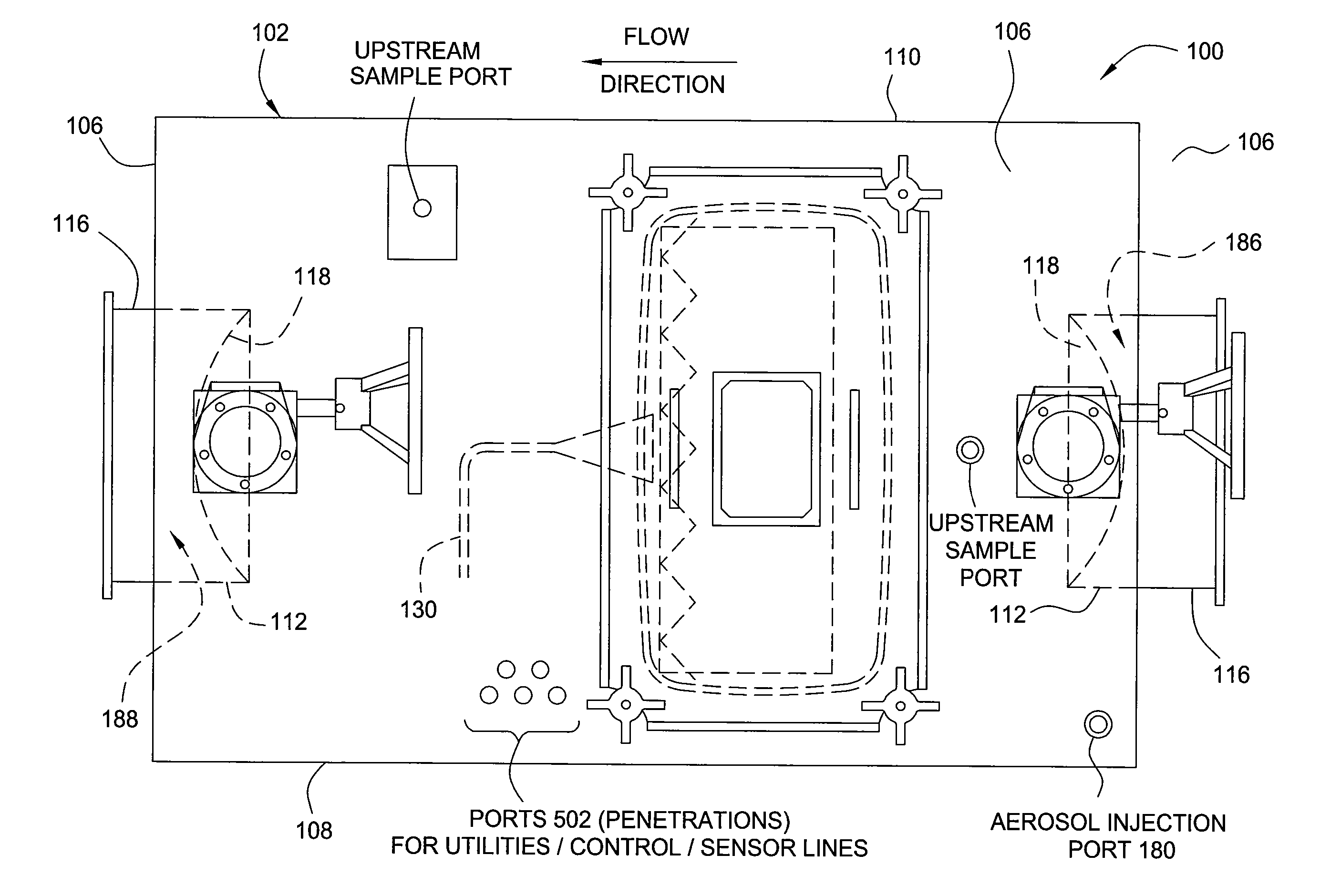
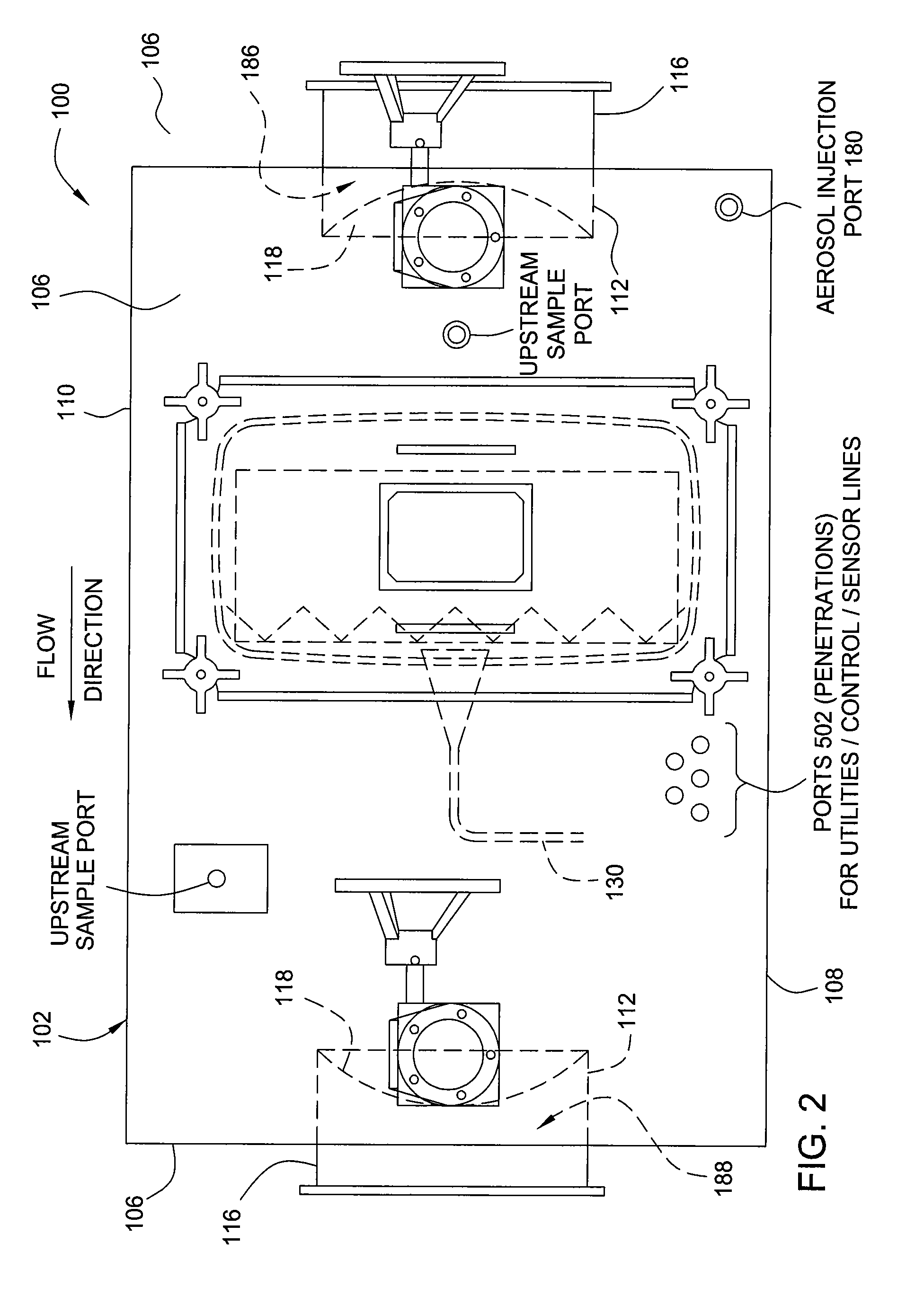
"The invention provides a containment system with bubble tight-dampers and an auto-scan mechanism for leak testing without accessing the interior of the housing. The method involves challenging the upstream side of a filter element with a test aerosol and automatically moving a probe to obtain samples for leak testing."

Problems solved by technology

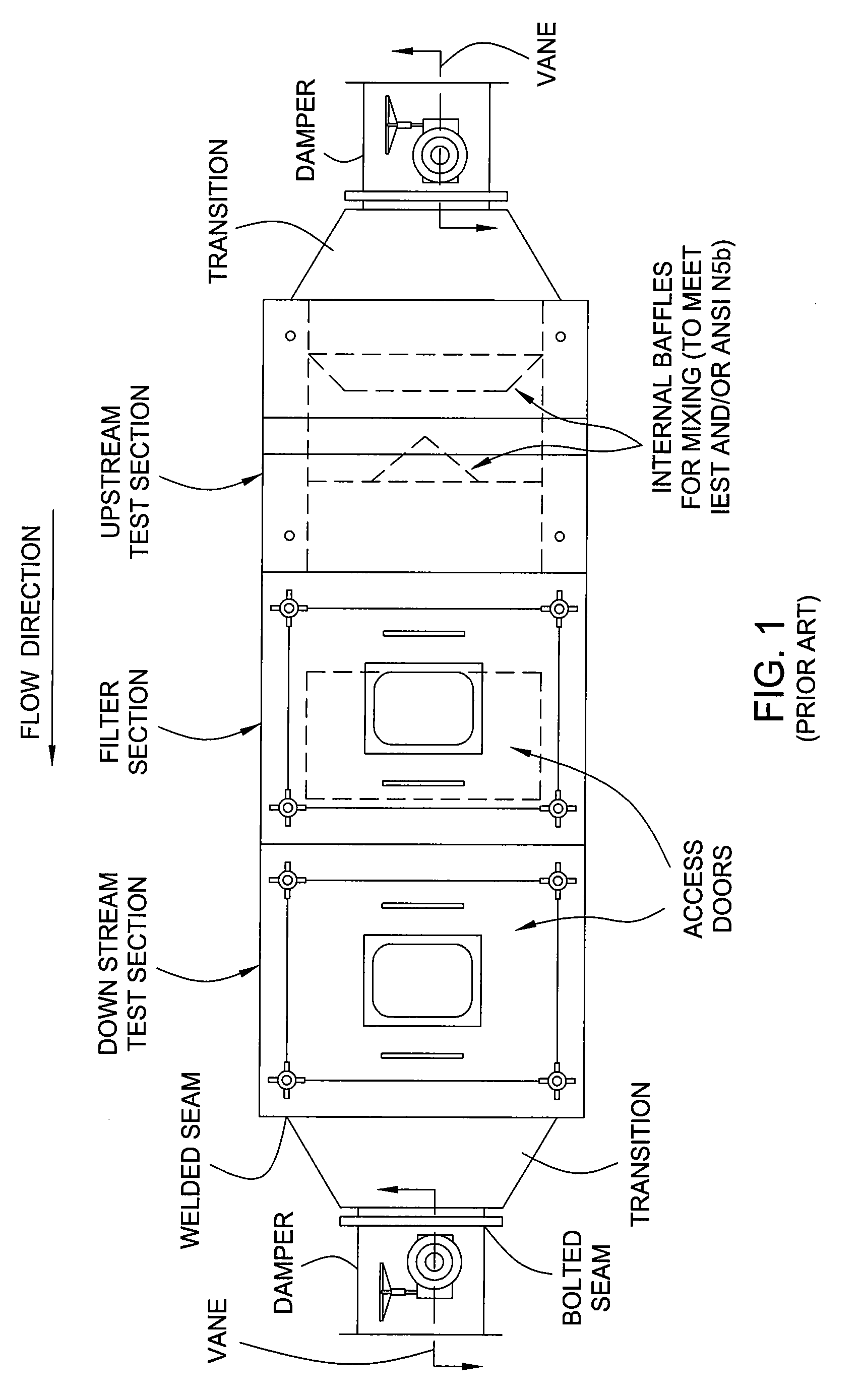
This configuration for a conventional containment system is very large, typically in the range of about 130 inches in length, and requires significant space and cost for installation.
Moreover, the large size of the components, typically fabricated from stainless steel, results in a high material costs.
Furthermore, each access door, bag ring, and joint between the multiple sections is a potential leak point.

Method used


Image

  • Integrated containment system
  • Integrated containment system
  • Integrated containment system

Examples


Embodiment Construction

[0024] The present invention includes one or more of the following features:

[0025] Filter housing(s) and test sections incorporated into a single housing, thereby eliminating potential leak points such as multiple bolted or welded connections of individual sections.

[0026] Damper blade and sealing surface are integrated into a containment housing as opposed to being a separate damper.

[0027] Damper utilizes the body of the containment housing as the external pressure boundary, as opposed to a separate housing such as the barrel of a damper (such as shown in the conventional system depicted in FIG. 1).

[0028] The damper “seal plate” or sealing surface and inlet flange are attached directly to the end of the containment housing. They are an integral part of the containment housing.

[0029] Beneficially, the integrated damper eliminates potential leak points such as multiple bolted or welded connections (e.g., such as the damper and transition shown in the conventional system depicted ...


PUM

PropertyMeasurementUnit
lengthaaaaaaaaaa
total lengthaaaaaaaaaa
concentrationaaaaaaaaaa

Abstract

Embodiments of the invention generally provide a containment system having integrated bubble tight-dampers. In another embodiment, the containment system includes an integral auto-scan mechanism disposed in the housing of the containment system so that a filter element, disposed in the housing, may be leak tested without accessing the interior of the housing. In yet another embodiment, a method for testing a filter disposed in a containment system includes challenging an upstream side of a filter element disposed in a housing of the containment system with a test aerosol, and automatically moving a probe disposed within the housing to obtain samples for leak testing.

Description

CROSS-REFERENCE TO RELATED APPLICATIONS [0001] This application claims benefit from U.S. Provisional Patent Application No. 60 / 706,516, filed Aug. 9, 2005 by Thomas C. Morse, which is incorporated by reference in its entirety. This application is a related to U.S. patent application Ser. No. ______, filed Apr. 28, 2005 by Thomas C. Morse entitled EXHAUST FILTER MODULE WITH MECHANICALLY POSITIONABLE SCAN PROBE, which is incorporated by reference in its entirety.BACKGROUND OF THE INVENTION [0002] 1. Field of the Invention [0003] The invention generally relates to a containment housing having integrated dampers. The invention also relates to a containment housing having an integrated filter leak scanning mechanism. [0004] 2. Description of the Related Art [0005]FIG. 1 depicts a conventional containment system. A conventional containment system typically consists of multiple components arranged in series. The components generally include one or more filter housing section, an upstream t...

Claims


Application Information

Patent Timeline
Patent Type & Authority Applications(United States)
IPC IPC(8): B01D45/00
CPCB01D46/0091B01D46/10B01D2273/18B01F5/0603B01F2005/0022G01M3/20G01N15/082Y10S55/31B23P6/00Y10T29/49826Y10T29/4973Y10T29/49764B01F2025/915B01F25/421
Inventor MORSE, THOMAS C.HUZA, MARK
Owner CAMFIL USA
Learn More