Electronic lock

a technology of electronic locks and locks, applied in the field of electronic locks, can solve problems such as lock failure to be unlocked

Inactive Publication Date: 2007-03-01
CHANG CHEN FEI
View PDF4 Cites 16 Cited by
  • Summary
  • Abstract
  • Description
  • Claims
  • Application Information

AI Technical Summary

Benefits of technology

[0008] The primary objective of the present invention is to provide an electronic lock, which is able to provide different effects by means of changing mount location of a solenoid in the electronic lock during a power-on and a power failure.

Problems solved by technology

However, when power off, the lock fails to be unlocked; hence, some makeup measures for unlocking the electronic lock must be taken into consideration.

Method used


Image

  • Electronic lock
  • Electronic lock
  • Electronic lock

Examples


Embodiment Construction

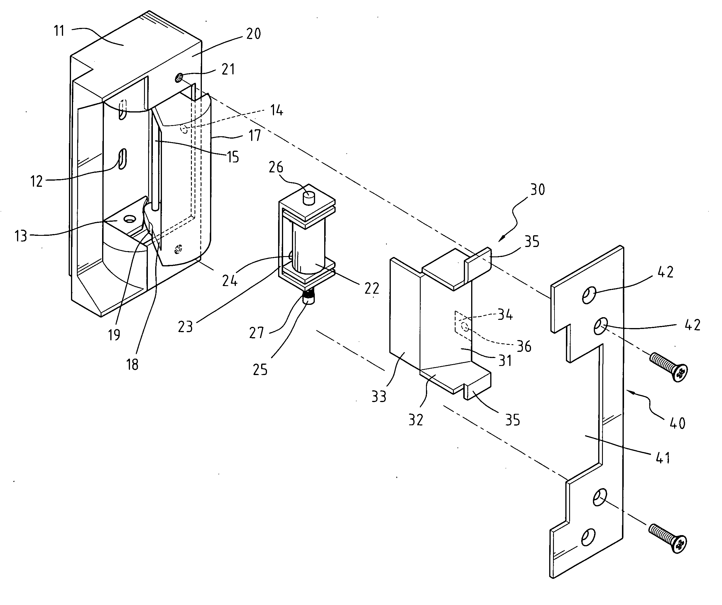
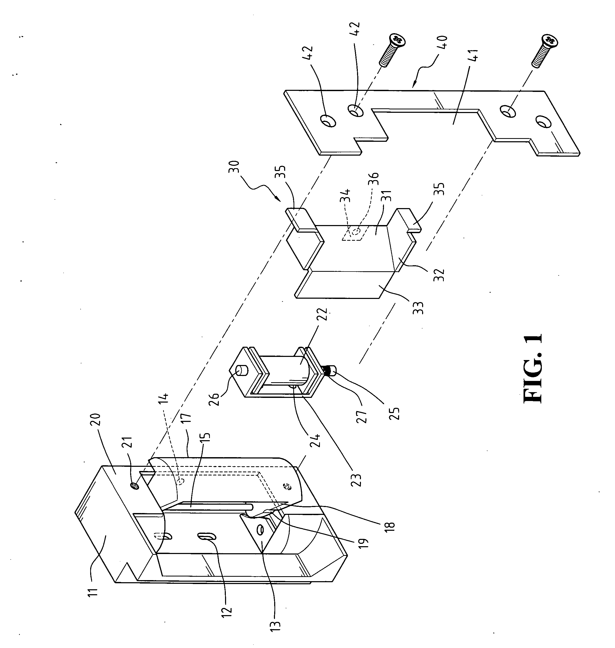
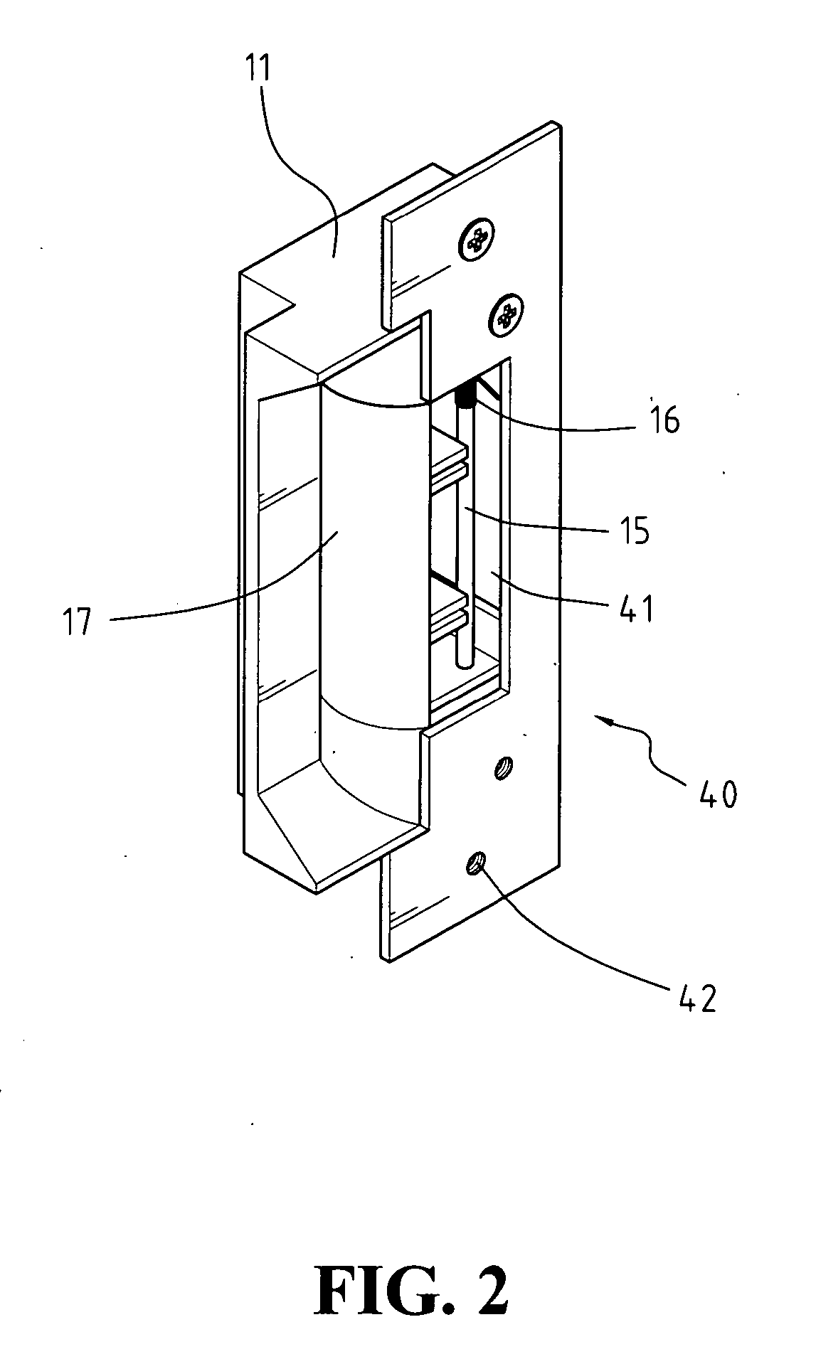
[0025] Referring to FIGS. 1-3, an electronic lock constructed in accordance with the present invention comprises a housing 11, a lock bar 17, a solenoid 22, a solenoid cover 30, and a faceplate 40.

[0026] The housing 11 is provided with two slots 12 and two brackets 13 on a base and a through hole 14 on a side face thereof. A torsion spring 16 is mounted to a pivot pin 15, and the pivot pin 15 is pivotably connected through two spaced laterally extending arms 18 extending from the lock bar 17 and then fixed to two ends of the housing 11. Each extending arm 18 has a notch 19 at a side thereof. The open side of the housing 11 forms two wing portions 20 at its top and bottom ends, each wing portion 20 having a screw hole 21 thereon. The lock bar 17 is received in the housing 11 and between the two wing portions 20.

[0027] The solenoid 22 is mounted to a frame 23 having two through holes 24 on a base thereof. The solenoid 22 has a retractable rod having a first end 25 and a second end 2...


PUM


Abstract

An electronic lock includes a housing, a solenoid, a lock bar, a solenoid cover, and a faceplate. The solenoid is received in and mounted to the housing and the solenoid has a retractable rod being spring biased to a first position when the solenoid is not energized and magnetically moved to a second position when the solenoid is energized. The lock bar is pivotably mounted to a pivot pin, and the pivot pin is mounted with a spring member and fixed to two ends of the housing. The solenoid cover is covered on the solenoid and the faceplate is mounted to the housing. The solenoid cover and the faceplate define a latch bolt cavity. When the solenoid is energized, the retractable rod is withdrawn to the second position, so that the lock bar can be transversely rotated, thereby detaching from a latch bolt and allowing a door to be opened.

Description

BACKGROUND OF THE INVENTION [0001] 1. Field of the Invention [0002] The present invention relates generally to electronic locks, and in particular to an electronic lock capable of providing different effects by means of changing mount location of a solenoid in the electronic lock during a power-on and a power failure. [0003] 2. The Prior Arts [0004] In order to ensure security of people's lives and properties, a conventional mechanical lock integrated with an electronic device becomes an electronic lock for guarding for example office buildings, which can be disabled only by a decoding measure. [0005] The conventional electronic lock mainly comprises a lock body and a sensor, in which the lock body is provided with a housing, a solenoid and a lock bar movable in transverse direction; the sensor is provided with a keyboard having a plurality of keys for setting a code or decoding, and a control circuit for controlling the operation of the electronic lock according to signals received...

Claims


Application Information

Patent Timeline
Patent Type & Authority Applications(United States)
IPC IPC(8): E05B15/02
CPCE05B47/0047Y10T292/699
Inventor CHANG, CHEN-FEI
Owner CHANG CHEN FEI
Why Eureka
Try Eureka