Remote intercom operator with finder

Inactive Publication Date: 2007-03-01
JOHNSTON ANTHONY
View PDF15 Cites 6 Cited by
  • Summary
  • Abstract
  • Description
  • Claims
  • Application Information

AI Technical Summary

Problems solved by technology

These systems generally work very well, however, they present certain problems for those with physical handicaps.
It is often difficult for such handicapped person to get to the intercom/re

Method used


Image

  • Remote intercom operator with finder
  • Remote intercom operator with finder
  • Remote intercom operator with finder

Examples


Example

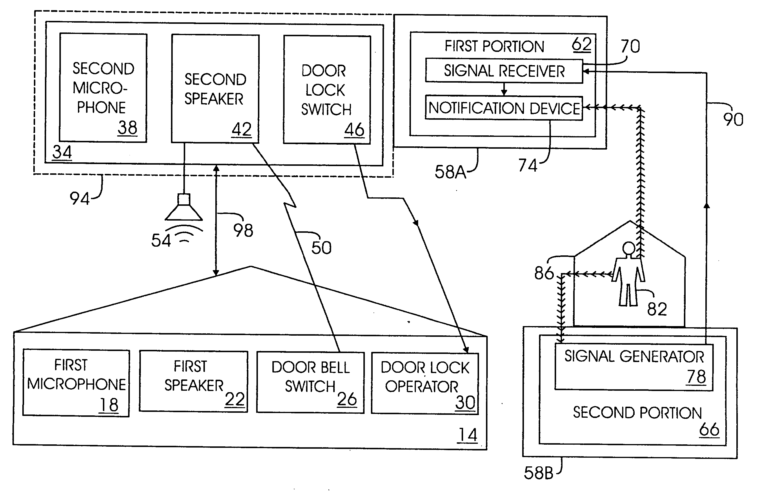
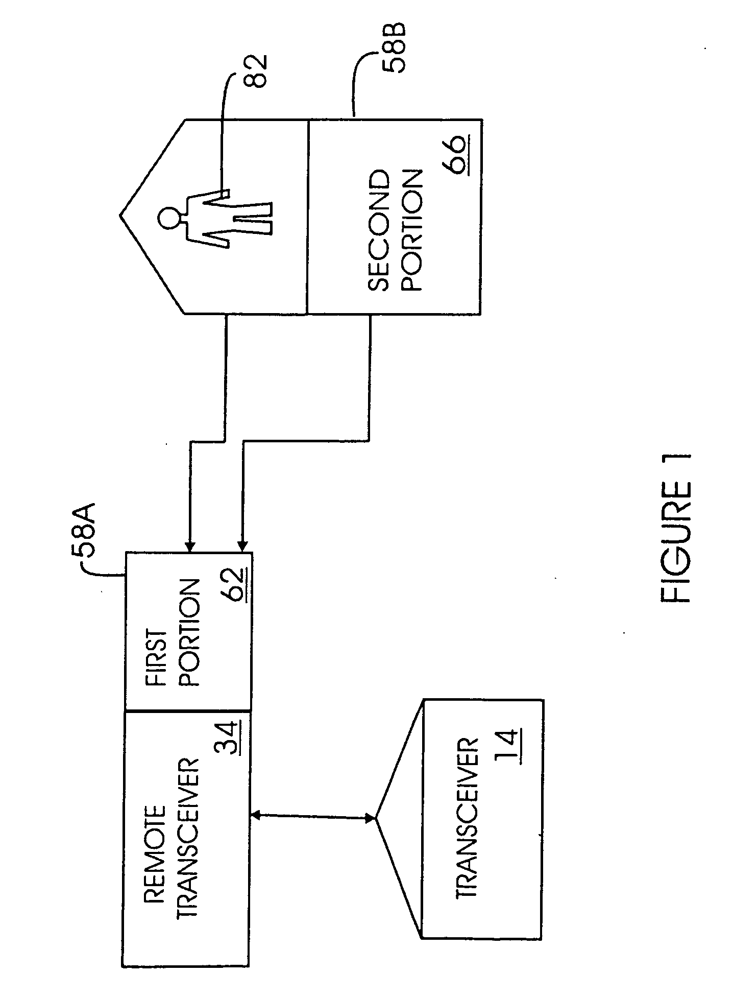
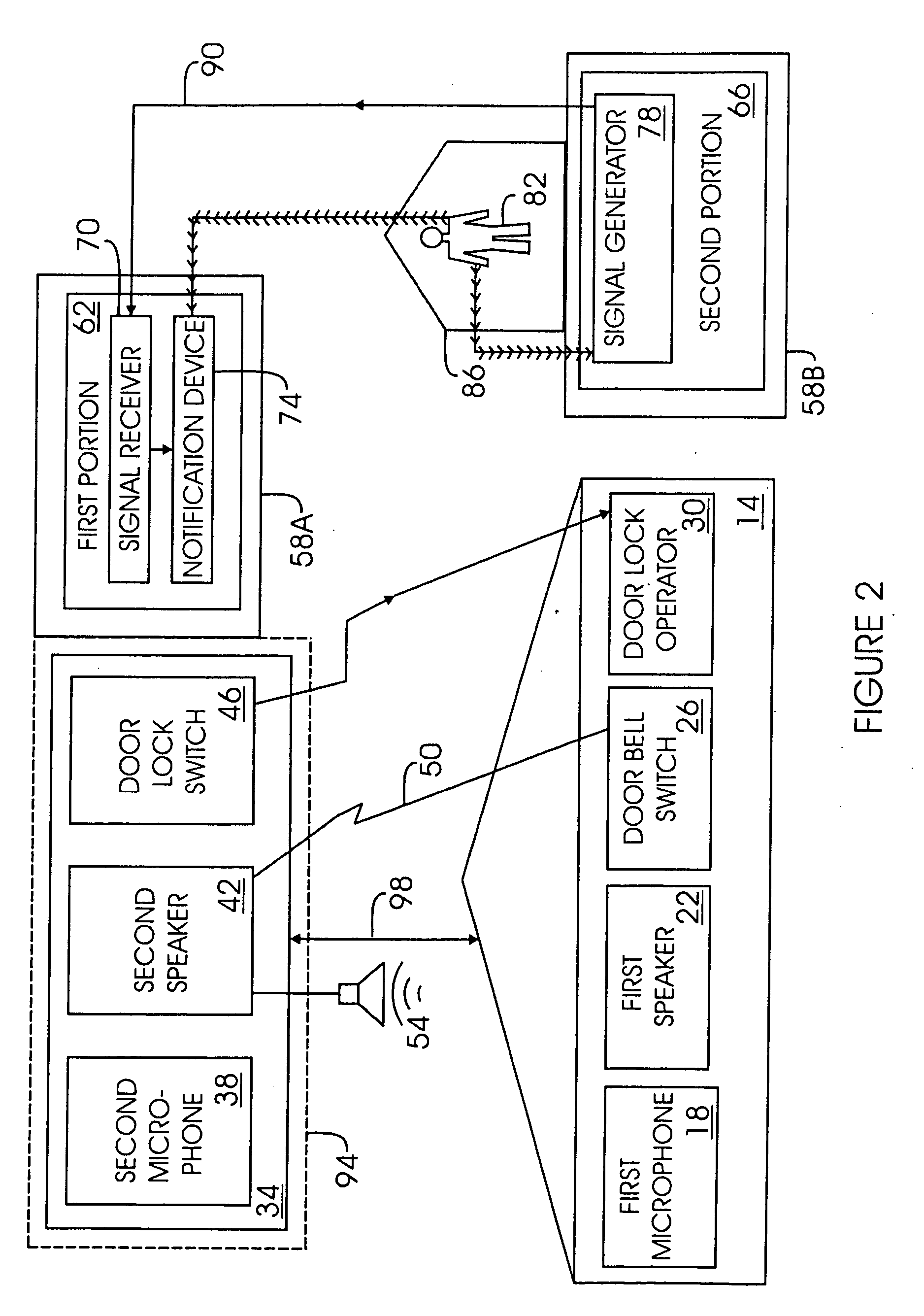
[0031] (1) FIGS. 1-5 illustrate a remote intercom operator with finder 10 having all of the desired features that can be constructed from the following components. An entryway mounted transceiver 14 is provided. The transceiver 14 includes a first microphone 18, a first speaker 22, a doorbell switch 26 and an electrical door lock operator 30. A remote transceiver 34 is provided. The remote transceiver 34 includes a second microphone 38, a second speaker 42 and a door lock switch 46. The doorbell switch 26 provides a signal 50 to the remote transceiver 34 and causes a sound 54 to be produced by the second speaker 42. The remote transceiver 34 provides two-way verbal communication with the entryway mounted transceiver 14. The door lock switch 46 operates the electrical door lock operator 30 from a remote location.

[0032] A remote finder 58A, 58B is provided. The remote finder 58A, 58B has a first portion 62 and a second portion 66. The first portion 62 is attached to the remote transc...


PUM


Abstract

A retaining-locking system for chain link fence slats includes specially notched fence slat elements having a pointed upper or lower end. The slat elements are sized and shaped to be interwoven between consecutive links of a chain link fence. A retaining-locking strip is formed of resilient material, and has an inner surface and an outer surface and at least one securing protrusion. The securing protrusion is sized and shaped to fit slidably within the notch. The protrusion is located on the outer surface of the strip. When the slat elements are interwoven into between consecutive links of a chain link fence with each of the notches aligned with one another, the retaining-locking strip inserted between the slat elements and the links, with the securing protrusion disposed within the slats, the strip will urge the slats toward the links, thereby retaining the slats within the chain link fence.

Description

FIELD OF INVENTION [0001] The invention pertains to remote control systems systems. More particularly, the invention relates to remote operational controls for home security and access systems. BACKGROUND OF THE INVENTION [0002] As home security becomes a serious concern for many homeowners, more and more homes and apartments are equipped with security systems for controlling entry through building doors. This is typically done in conjunction with an intercom system incorporating an electrically controlled door lock at a remote location. In use, the person desiring entry will actuate a doorbell or buzzer which rings inside of the home or apartment of the occupant. The occupant will then use the intercom system to enquire who is at their door. Upon receiving a satisfactory answer, the occupant will activate the remote door lock to allow the person entry. These systems generally work very well, however, they present certain problems for those with physical handicaps. It is often diffi...

Claims


Application Information

Patent Timeline
IPC IPC(8): H04N7/18
CPCG07C9/00166H04N7/186H04M11/025G07C9/38
Inventor JOHNSTON, ANTHONY
Owner JOHNSTON ANTHONY
Why Eureka
Try Eureka